CHAPTER 3: DNP COMMUNICATION
DNP POINTS
D90
PLUS
LINE DISTANCE PROTECTION SYSTEM – COMMUNICATIONS GUIDE
213
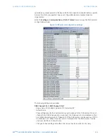
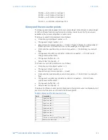
Point 64
→
automation virtual input 1
Point 65
→
automation virtual input 2
Point 66
→
automation virtual input 3
...
Point 191
→
automation virtual input 128
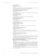
Binary and frozen counter points
The following description applies to binary counters (object 20) and frozen counters (object
21). When a freeze function is performed on a binary counter point, the frozen value is
available in the corresponding frozen counter point.
The binary counter DNP parameters are as follows:
•
Static (steady-state) object number — 20
•
Change event object number — 22
•
Request function codes supported — 1 (read), 7 (freeze), 8 (freeze, no acknowledge), 9
(freeze and clear), 10 (freeze and clear, no acknowledge), 22 (assign class)
•
Static variation reported when variation 0 requested — 1 (32-bit binary counter with
flag)
•
Change event variation reported when variation 0 requested: — 1 (32-bit counter
change event without time)
•
Change event buffer size — 10
•
Default class for all points — 3
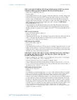
The frozen counter DNP parameters are as follows:
•
Static (steady-state) object number — 21
•
Change event object number — 23
•
Request function codes supported — 1 (read)
•
Static variation reported when variation 0 requested — 1 (32-bit frozen counter with
flag)
•
Change event variation reported when variation 0 requested — 1 (32-bit frozen
counter event without time)
•
Change event buffer size —10
•
Default class for all points — 3
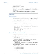
The binary and frozen counter points correspond to the digital counter, oscillography, and
event recorder functions as indicated in the following table.
Table 11: Binary and frozen counter points
Point
Description
0
Digital counter 1
1
Digital counter 2
2
Digital counter 3
3
Digital counter 4
4
Digital counter 5
5
Digital counter 6
6
Digital counter 7
7
Digital counter 8
8
Transient record newest file number
9
Events since last clear

