


CHAPTER 3: DNP COMMUNICATION
DNP DEVICE PROFILE
D90
PLUS
LINE DISTANCE PROTECTION SYSTEM – COMMUNICATIONS GUIDE
211
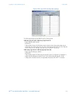
DNP Current Default Deadband, DNP Voltage Default Deadband, DNP Power Default
Deadband, DNP Energy Default Deadband, DNP Other Default Deadband
Range: 0 to 100000000 in steps of 1
Default: 30000
These settings determine when to trigger unsolicited responses containing analog input
data. These settings group the D90
Plus
analog input data into types: current, voltage,
power, energy, and other. Each setting represents the default deadband value for all
analog input points of that type. For example, to trigger unsolicited responses from the
D90
Plus
when any current values change by 15 amps, configure the
DNP Current
Default Deadband
setting to “15.”
These settings are the deadband default values. DNP object 34 points can be used to
change deadband values from the default for each individual DNP analog input point.
Whenever power is removed and re-applied to the D90
Plus
, the default deadbands are in
effect.
DNP Time Sync IIN Period
Range: 1 to 10080 minutes in steps of 1
Default: 1440 minutes
This setting determines how often the Need Time Internal Indication (IIN) bit is set by the
D90
Plus
. Changing this time allows the DNP master to send time synchronization
commands more or less often, as required.
DNP Message Fragment Size
Range: 30 to 2048 in steps of 1
Default: 240
This setting determines the size, in bytes, at which message fragmentation occurs. Large
fragment sizes allow for more efficient throughput; smaller fragment sizes cause more
application layer confirmations to be necessary, which can provide for more robust data
transfer over noisy communication channels.
DNP Object 1 Variation, DNP Object 2 Variation, DNP Object 20 Variation, DNP Object
21 Variation, DNP Object 22 Variation, DNP Object 23 Variation, DNP Object 30
Variation, DNP Object 32 Variation
Range: 1, 2 (object 1); 1, 2, 3 (object 2); 1, 2, 5, 6 (objects 20, 22, and 23); 1, 2, 9, 10 (object
21); 1, 2, 3, 4, 5 (object 30); 1, 2, 3, 5, 7 (object 32)
Default: 1 (objects 20, 21, 22, 23, 30, and 32); 2 (objects 1 and 2)
These settings select the DNP default variation number for object types 1, 2, 20, 21, 22,
23, 30, and 32. The default variation refers to the variation response when variation 0 is
requested and/or in class 0, 1, 2, or 3 scans.
DNP Number of Paired Controls
Range: 0 to 32 in steps of 1
Default: 0
The DNP binary outputs typically map one-to-one to IED data points. That is, each DNP
binary output controls a single physical or virtual control point in an IED. In the D90
Plus
,
DNP binary outputs are mapped to protection and/or automation virtual inputs.
However, some legacy DNP implementations use a mapping of one DNP binary output
to two physical or virtual control points to support the concept of trip/close (for circuit
breakers) or raise/lower (for tap changers) using a single control point. That is, the DNP
master can operate a single point for both trip and close, or raise and lower, operations.
The D90
Plus
can be configured to support paired control points, with each paired control
point operating two virtual inputs (protection or automation). This setting allows
configuration of 0 to 32 binary output paired controls. Points not configured as paired
operate on a one-to-one basis.


