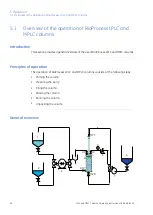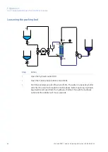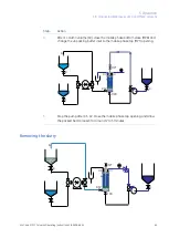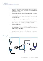
The schematic diagram above illustrates the main features and equipment used in
priming, packing and unpacking BioProcess LPLC and MPLC columns.
Description
Part
Slurry tank
1
Water/buffer tank
2
Filling pump (membrane pump)
3
Pressure gauge
4
Pressure relief valve
5
Hydraulic fluid tank
6
Packing pump (rotary lobe or equivalent)
7
Hydraulic outlet
HO
Hydraulic inlet
HI
Mobile phase top valve
MPT
Bottom slurry valve
BSV
Mobile phase bottom valve
MPB
LPLC and MPLC Columns Operating Instructions 28-9638-66 AC
51
5 Operation
5.1 Overview of the operation of BioProcess LPLC and MPLC columns

