Register
your product
www.kaercher.com/welcome
9.808-341.0-E 12/19/22
HDS, LFT SERIES
Hot Water - Gas Powered - Diesel Heated
English 02
LISTED
®
OPERATOR’S MANUAL
Page 1: ...Register your product www kaercher com welcome 9 808 341 0 E 12 19 22 HDS LFT SERIES Hot Water Gas Powered Diesel Heated English 02 LISTED OPERATOR S MANUAL...
Page 2: ...2 9 808 341 0 E Operator s Manual LFT Machine Data Label MODELS HDS 5 0 40 LFT 1 110 101 0 HDS 8 0 30 LFT 1 110 102 0 HDS 5 0 35 LFT 1 110 103 0 HDS 8 0 30 LFT 1 110 104 0...
Page 3: ...ntative Maintenance 16 Maintenance And Service 17 Unloader Valves 17 Winterizing Procedure 17 High Limit Hot Water Thermostat 17 Pumps 17 Cleaning of Coils 17 Rupture Disk 17 Fuel 18 Burner Nozzle 18...
Page 4: ...omponents in good working condition They are listed in this general order Storage Engine Maintenance Preventative Maintenance Maintenance And Service Unloader Valves Winterizing Procedure High Limit H...
Page 5: ...h the operator in the operator s native language by the purchaser owner making sure that the operator comprehends its contents Owner and or user must study and maintain for future reference the manufa...
Page 6: ...ide full protection 6 Keep operating area clear of all persons WARNING Flammable liquids can create fumes which can ignite causing property damage or severe injury AVERTISSEMENT Des liquides inflammab...
Page 7: ...or death will result ATTENTION Liquide de d charge chaud Ne pas d charger directement le jet vers des personnes ou des animaux car cela risquerait de causer des blessures graves ou m me la mort WARNI...
Page 8: ...drainage ad quats pour r duire la possibilit d une chute due une surface glissante 21 Do not allow acids caustic or abrasive fluids to pass through the pump 22 Never run pump dry or leave spray gun cl...
Page 9: ...t Safety control which prevents temperatures from going above adjustable setting Wand Must be connected to the spray gun NOTE If trigger on spray gun is released for more than 2 minutes warm water wil...
Page 10: ...ector and turn on water supply CAUTION Do not run the pump without water or pump damage will result ATTENTION Ne pas faire fonctionner la pompe sans eau ou des d g ts de pompe se produiront STEP 3 Rem...
Page 11: ...fety and installation instructions furnished with the battery Red Cable is attached to battery positive terminal black cable is connected to battery negative terminal 9 808 341 0 E Operator s Manual L...
Page 12: ...r to shut off engine IMPORTANT Do not run engine with high or low oil levels as this will cause engine damage STEP 5 Pull the choke lever out to the Choke position on a warm engine leave the choke lev...
Page 13: ...sur le cordon de lancement Tirer lentement sur le cordon de lancement jusqu ce qu une r sistance soit sentie puis tirer rapidement STEP 7 Electric Start Models Turn the engine switch to Start position...
Page 14: ...with fresh water Place detergent suction tube directly into cleaning solution and apply to surface at low pressure for best results limit your work area to sections approximately 6 feet square and al...
Page 15: ...tch off and continue spraying allowing the water to cool to below 100 F STEP 4 Press trigger to release water pressure STEP 7 Disconnect the high pressure hose from high pressure outlet STEP 2 Turn of...
Page 16: ...additive such as STA BIL or an equivalent will minimize the formulation of fuel deposits during storage Such additives may be added to the gasoline in the fuel tank of the engine or to the gasoline in...
Page 17: ...matically reset itself The thermo stat sensor is located on the discharge side of the heating coil The thermostat control dial is located on the control panel Pumps Before running the pump check the p...
Page 18: ...ge may require the heat input to be lowered so the water input does not turn to steam earlier than at the factory settings and activate the pressure sensors and pressure relief equipment when the unit...
Page 19: ...start up or operation discon tinue use and readjust air bands ATTENTION Si de la fum e blanche s chappe de l vacuation du br leur pendant le d marrage ou le fonctionnement cesser d utiliser et r ajus...
Page 20: ...asher Perform maintenance more often under severe conditions Check pump oil level before first use of your new pressure washer Change pump oil after first 50 hours and every year or 500 hours thereaft...
Page 21: ...nge Record PUMP OIL DateOilChanged Month Day Year Estimated Operating Hours Since Last Oil Change ENGINE OIL DateOilChanged Month Day Year Estimated Operating Hours Since Last Oil Change 9 808 341 0 E...
Page 22: ...tion Leaking pressure control valve Rebuild or replace as needed Slow engine RPM Set engine speed at proper specifications Pump sucking air Check water supply and possibility of air seepage Valves sti...
Page 23: ...gine altitude The gasoline engine is preset for operation at altitudes below 1000 ft above sea level If operated at higher altitudes it may be necessary to install a high altitude main jet in the carb...
Page 24: ...eplace Incorrect fuel nozzle size See specifications for proper fuel nozzle Insufficient water supplied Check water G P M to machine Restricted water flow Check nozzle for obstruction proper size PUMP...
Page 25: ...ergent line s Repair hole Low detergent level Add detergent if needed PUMP RUNNING NORMALLY BUT PRESSURE LOW ON INSTALLATION Pump sucking air Check water supply and possibility of air seepage Valves s...
Page 26: ...26 Notes 9 808 341 0 E Operator s Manual LFT...
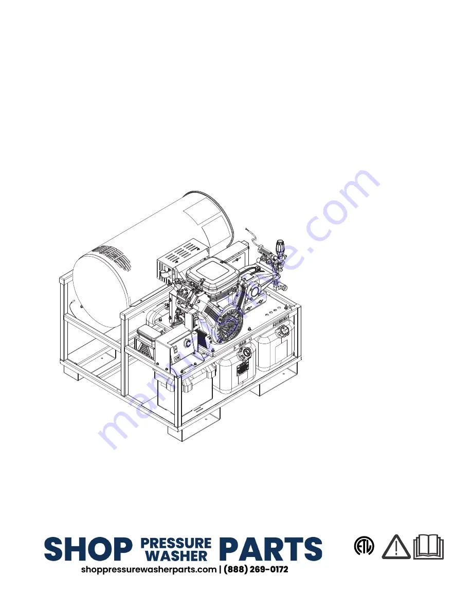
Page 27: ...27 Parts Parts LFT HDS HDS 5 0 40 LFT 1 110 101 0 HDS 8 0 30 LFT 1 110 102 0 HDS 5 0 35 LFT 1 110 103 0 HDS 8 0 30 LFT 1 110 104 0 9 808 341 0 E Operator s Manual LFT...
Page 28: ...28 LFT HDS 9 808 341 0 E Operator s Manual LFT See Engine Assy For Details 20 1 2 3 4 80 79 5 6 18 19 17 22 7 8 10 9 11 12 13 23 26 27 24 15 16 33 21 14 25 27 28 29 30 31 32 36 36 38 37 39 39 35...
Page 29: ...29 9 808 341 0 E Operator s Manual LFT LFT HDS 40 58 41 42 43 45 46 48 49 52 52 67 67 61 47 51 44 44 71 76 54 55 62 65 64 63 69 50 56 77 66 68 59 78 60 53 68 70 57 75 74 72 73...
Page 30: ...8 706 553 0 6 MOUNT RUBBER 60 DURO 21 9 802 778 0 12 NUT 5 16 WHIZ LOC FLANGE 22 8 930 784 0 1 CONTROL PANEL BASE 23 9 802 754 0 10 SCREW 1 4 X 1 2 NC WHIZ LOC FLANGE 24 8 930 801 0 1 CONTROL PANEL T...
Page 31: ...E 18HP VANGUARD 20AMP NO TANK 1 110 103 0 60 8 759 746 0 1 GASOLINE ENGINE LONCIN 25HP 1 110 101 0 1 110 102 0 60 8 759 777 0 1 ENGINE 23HP VANGUARD 20AMP NO TANK 1 110 104 0 61 9 802 673 0 1 KEY SHAF...
Page 32: ...32 Pump Leuco LT6036R 9 808 341 0 E Operator s Manual LFT 5 6 3 14 13 15 7 9 8 20 11 5 4 16 17 19 17 10 1 8 930 831 0 for model 1 110 103 0...
Page 33: ...PP M 8 8 757 203 0 1 SWIVEL 1 2 M NPTF X 3 4 GHF 9 8 757 257 0 1 TEE STREET 1 2 10 8 757 262 0 1 ELBOW BRASS 1 2 SAE M X 3 8 NPTF M 11 8 757 340 0 1 ELBOW 3 8 STREET 90 DEG STEEL W SLNT 12 8 757 616 0...
Page 34: ...34 Pump Leuco 9536R 9 808 341 0 E Operator s Manual LFT 15 22 16 10 7 16 9 20 12 8 11 14 1 21 4 3 2 3 13 17 8 930 857 0 for model 1 110 102 0...
Page 35: ...9 8 757 617 0 1 ELBOW STEEL 1 2 JIC M X 1 2 BSPP M 10 8 757 616 0 1 ELBOW STEEL 1 2 JIC M X 3 8 BSPP M 11 8 757 485 0 1 TEE 1 2 BRASS 12 8 757 340 0 1 ELBOW 3 8 STREET 90 DEG STEEL W SLNT 13 8 757 262...
Page 36: ...36 Pump Leuco 5843R 9 808 341 0 E Operator s Manual LFT 5 7 1 6 3 18 14 17 15 8 16 12 9 23 11 2 4 20 21 22 10 19 8 931 564 0 for model 1 110 101 0...
Page 37: ...NPTF X 3 4 GHF 10 8 757 262 0 1 ELBOW BRASS 1 2 SAE M X 3 8 NPTF M 11 8 757 340 0 1 ELBOW 3 8 STREET 90 DEG STEEL W SLNT 12 8 757 485 0 1 TEE 1 2 BRASS 13 8 757 513 0 1 BUSHING 1 2 NPTF M X 3 8 NPTF...
Page 38: ...38 Engine Gasoline Tank 6 5 1 7 13 8 9 10 11 15 6 17 16 21 19 18 20 20 18 4 22 23 3 14 21 To Tank 2 To Engine Purge 9 808 341 0 E Operator s Manual LFT...
Page 39: ...056 0 1 DIP TUBE ASSY PLASTIC 10 75 9 9 802 053 0 1 BUSHING MOLDED 10 8 751 057 0 1 CAP FUEL TANK W GAUGE RATCHET 11 9 800 001 0 1 LABEL GASOLINE ONLY 12 9 802 254 0 18 HOSE 1 4 FUEL 13 9 802 254 0 10...
Page 40: ...ONG 3 8 750 933 0 2 BAND HOSE CLAMP HOSE ID 1 8 5 16 4 9 802 254 0 36 HOSE 1 4 PUSH ON FUEL 5 9 802 053 0 2 BUSHING MOLDED 6 9 803 535 0 1 CAP FUEL TANK W GAUGE 7 9 800 002 0 1 LABEL USE ONLY KEROSENE...
Page 41: ...ROMMET RUBBER NOZZLE HOLDER 4 9 802 762 0 1 SCREW 10 32 X 1 1 41 5 8 706 745 0 1 PLUG PLASTIC 6 9 802 700 0 4 BOLT 1 4 X 3 4 NC HH 7 9 802 480 0 1 BOX PLASTIC BACK 8 9 802 514 0 4 STRAIN RELIEF STRAIG...
Page 42: ...ROL BOX 15 9 802 771 0 3 SCREW 10 32 X 3 4 BH SOC CS 16 9 802 283 0 1 HOUR METER 120V 17 9 802 451 0 1 SWITCH ROCKER CARLING W GREEN LENS 18 8 712 190 0 1 PLATE THERMOSTAT PLASTIC COVER 19 8 718 779 0...
Page 43: ...YELLOW 1 110 101 0 4 8 712 381 0 1 NOZZLE SAQC MEG 4009 1 110 102 0 4 8 712 380 0 1 NOZZLE SAQC MEG 2509 1 110 102 0 4 8 712 379 0 1 NOZZLE SAQCMEG 1509 1 110 102 0 4 8 712 356 0 1 NOZZLE SAQCMEG 4005...
Page 44: ...80 B 8 700 947 0 1 110 103 0 BURNER EHASR 12VDC DO 2T 12VDC S 8 756 480 0 FUEL NOZZLE 2 50 X 80 B 8 700 947 0 MODEL PUMP MODEL PUMP PART UNLOADER PULLEY PULLEY PART BUSHING BUSHING PART 1 110 101 0 5...
Page 45: ...45 Wayne Burner EHASR DC 9 808 341 0 E Operator s Manual LFT...
Page 46: ...00 704 0 1 OIL LINE 6 11 8 756 437 0 1 PUMP COMBO W SOLENOID 12V 24V 12 13494 1 BRASS 90 ELBOW 13 8 700 819 0 1 CAD CELL F HS M SERIES BURNE 8 756 661 0 1 TIMER BURNER DROP OUT 14 8 756 299 0 1 GUN AS...
Page 47: ...6 13392 1 SLOT COVER PLATE 7 8 700 732 0 1 BAND AIR BURNER INNER EHA SR 8 8 700 729 0 1 AIR BAND 8 HOLE OUTER EHA SR 9 8 700 776 0 1 COUPLING A B PUMP 10 8 700 704 0 1 OIL LINE 6 11 8 756 290 0 1 PUMP...
Page 48: ...804 498 0 6 O RING 2 62 X 25 1 SEE KITS TABLE 12 6 VALVE ASSEMBLY SEE KITS TABLE 13 9 803 193 0 6 O RING 3068 SEE KITS TABLE 14 9 802 928 0 6 VALVE PLUG 15 8 753 817 0 8 MANIFOLD STUD BOLT 16 9 802 89...
Page 49: ...752 820 0 3 BONDED SEAL SEE KITS TABLE 36 8 753 819 0 3 PLUNGER 18MM SEE KITS TABLE 37 8 752 823 0 3 COPPER SPACER SEE KITS TABLE 38 8 753 820 0 3 PLUNGER ROD 39 8 752 822 0 3 CONNECTING ROD PIN 40 8...
Page 50: ...NLOADER 8 750 709 0 REPAIR KIT VRT3 2320 3630 PSI 8 750 710 0 REPAIR KIT VRT3 4500 PSI KIT ITEMS 3 4 6 9 12 21 24 8 750 297 0 8 GPM 2320 PSI 8 750 298 0 8 GPM 3630 PSI 8 750 299 0 8 GPM 4500 PSI 9 8 2...
Page 51: ...d screw down until contact is made with the nuts Items 15 Screw down lock nut Item 19 onto the stem Item 8 until the threads cut into the nylon insert of the lock nut Item19 If adjustment knob Item 18...
Page 52: ...XT STEPS 9 808 341 0 E Operator s Manual LFT STEP 2 Fasten the following screws 2 6x12 Included with machine STEP 1 Place the air filter on top of the engine STEP 3 Connect both hoses add clamp Includ...
Page 53: ...52 9 808 341 0 E Operator s Manual LFT Loncin Engine Steps STEP 5 Connect hose from canister...
Page 54: ...Karcher North America 6398 N K rcher Way Aurora CO 80019 Form 9 808 341 0 Revised 11 22 Printed in U S A or Mexico...