


3—Installation and Wiring
Intraplex NetXpress IP Multiplexer
Version 3.05
GatesAir, Inc.
3-9
Intraplex Products
On the rear of the NetXpress chassis, the main power supply is on the far left, and the redundant
power supply—if present—is right of the main supply. As there is no power switch on the NetXpress
shelf, do not connect powered AC line cords to the NetXpress chassis until you complete the wiring to
the network and channel modules. If you are using redundant power supplies, you need two power
cords.
A chassis ground connection is available on the rear panel (circled in red in Figure 3-8) just above the
ALARMS terminal. This needs to be connected to an appropriate system ground for safety.
1.
Install the channel modules into the slots.
Note:
The TDM Channel module may initialize in an “out-of-service” state, requiring activation
through the Web Interface or SNMP.
2.
Verify that all modules (NIM-1, CAM, TDM Channel, and Power) are seated snugly.
3.
If the shelf is AC powered, plug the AC line cord into the appropriate AC input connector. If you
have redundant AC supplies, plug both AC line cords into the appropriate AC input connectors.
4.
If the shelf requires DC power, hook the appropriate wires to the DC terminal connector.
3.10.1.2 DC Powered Systems
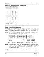
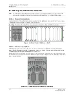
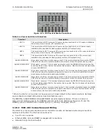
If the NetXpress chassis contains factory-installed DC power supplies, a barrier terminal strip is
present on the rear panel for connections to the DC power sources. Figure 3-8 shows the rear panel
connectors for the Intraplex NetXpress equipment shelf with AC and DC power capability. Table 3-4
describes the terminals on the DC power input barrier strip.
Figure 3-8. Rear Panel of NetXpress Shelf
Metal bridging links are included on the DC barrier strip to connect both positive power terminal input
leads together and to link the negative power input leads together. This permits a single external DC
source to supply power to both the main and redundant supplies. If you wish to independently source
the main and the redundant supplies, you need to remove these bridging clips from the barrier
terminals.
You should install an external fuse in the DC-power line to protect the multiplexer. The fuse rating is
6.3A for -48 volt input or 10A for -24 volt input. Remove this fuse and do not replace it until you
complete the rest of the system wiring and are ready to turn on the system.
Warning!
This fuse must be provided, both to protect the multiplexer and to provide a safe means of
removing power from a DC-powered shelf. Two are required for power-redundant systems.
1.
Connect the +BAT A terminal to the positive terminal of the station battery.
2.
A chassis ground connection is available on the rear panel just above the ALARMS terminal. This
needs to be connected to an appropriate system ground for safety.
3.
Connect the –BAT A terminal to the negative terminal of the station battery.
Summary of Contents for Intraplex NetXpress
Page 2: ......
Page 54: ...No header here 3 16 GatesAir Inc Intraplex Products This page is left blank intentionally...
Page 146: ...No header here 4 92 GatesAir Inc Intraplex Products This page is left blank intentionally...
Page 154: ...No header here 6 4 GatesAir Inc Intraplex Products This page is left blank intentionally...
Page 163: ...No header here GatesAir Inc 7 9 Intraplex Products This page is left blank intentionally...


