ANITA ©
14
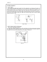
4.3) Timing Adjustment of Needle and Hook
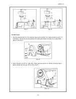
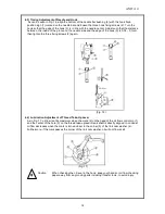
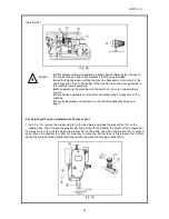
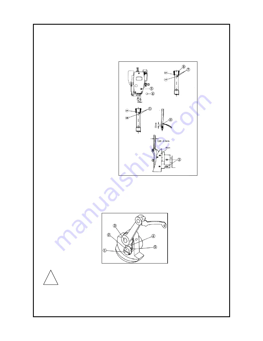
As can be seen in Fig. 16, align the bottom of the needle bar bushing (6) with the hook fixed
position sign (1) marked on the needle bar and loosen the three hook fixing screws (2). Turn the
hook so that the edge of the hook (3) is in line with the needle center. Adjust such that the distance
between the inside of the groove on the needle side and the edge of the hook (3) is 0,05 - 0,1mm,
then tighten the three fixing screws (2) again.
(Fig. 16)
4.4) Lubrication Adjustment of Thread Take-Up Lever
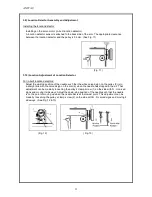
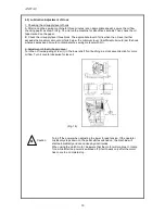
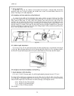
As in Fig. 17, oil flow is at its maximum when the mark (2) on the head of the oil flow control pin (1)
and the center of the hole (3) on the thread take-up lever crank shaft is directly aligned. In contrast,
oil flow decreases when the mark is turned closer to the corner (5) of the link cam washer (4).
Furthermore, if the mark passes the corner of the link cam washer, oil will not flow at all.
(Fig. 17)
Caution
When checking the oil level in the hook, keep your hands or oil flow checking
paper away from any moving parts including transfer tools, to avoid injury.
!
Summary of Contents for GF-1116 Series
Page 30: ...ANITA 30...


