background image

Garmin GI 275 Pilot's Guide

190-02246-01  Rev. A

81

Navigation

System Overview

Flight Instruments

EIS

Navigation

Hazar

d A
voidance

Autopilot

Additional F

eatur

es

Appendices

Index

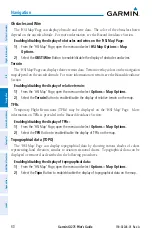
Track Vector

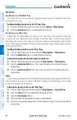
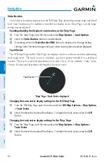
The 'HSI Map' Page and the 'Map' Page can display a track vector that is useful in minimizing 

track angle error.  The track vector is a dashed cyan line segment extended to a predicted 
location.  The track vector look-ahead time is selectable (30 sec, 60 sec (default), 2 min, 5 min, 
10 min, 20 min) and determines the length of the track vector. 

Changing the track vector display settings:
1) 

From the 'HSI Map' Page, open the menu and select 

Options

 > 

Map Options > Map 

Options > Track Vector

.

2) 

Select the 

Track Vector

 Button. Select the button again, as necessary, to cycle through 

each option and choose the desired setting.

Traffic

The 'HSI Map' Page can display traffic information.  Traffic may or may not be shown 

depending on the other aircraft's location and equipment.  For more information on traffic and 
traffic options, see the Hazard Avoidance Section.

Enabling/disabling the display of traffic:
1) 

From the 'HSI Map' Page, open the menu and select 

Options

 > 

Map Options

.

2) 

Select the 

Traffic 

Button to enable/disable the display of traffic on the map.

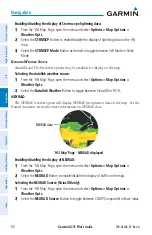
Weather Legend

A legend for weather products is available.  The legend will display information for each 

weather option that is enabled and displayed on the map.  For more information on how to 
display weather products on the map, see the following Weather Options discussion.

Viewing the Weather Legend:
1) 

From the 'HSI Map' Page, open the menu and select 

Options > Map Options

.

2) 

Select the 

Weather Legend 

Button to view the legend.

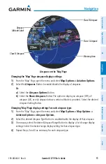
Weather Options

The 'HSI Map' Page can display Stormscope lightning and various types of datalink weather 

information.  Weather options may or may not be available depending on the configured 
equipment and subscription status, if applicable.  For more information on Stormscope and 
datalink weather, see the Hazard Avoidance Section.

S

tOrMSCOpe

 l

igHtning

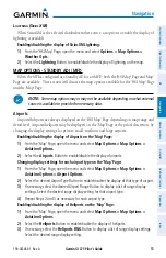
Stormscope lightning data may be overlaid on the navigation map.  See the Hazard Avoidance 

section for more information on lightning data.

Summary of Contents for GI 275

Page 1: ...GI 275 Pilot s Guide ...

Page 2: ......

Page 3: ...SYSTEM OVERVIEW FLIGHT INSTRUMENTS EIS NAVIGATION HAZARD AVOIDANCE AUTOPILOT ADDITIONAL FEATURES APPENDICES INDEX ...

Page 4: ......

Page 5: ...ants permission to download a single copy of this manual and of any revision to this manual onto a hard drive or other electronic storage medium to be viewed for personal use provided that such electronic or printed copy of this manual or revision must contain the complete text of this copyright notice and provided further that any unauthorized commercial distribution of this manual or any revisio...

Page 6: ...NING Do not rely solely upon the display of traffic information to accurately depict all of the traffic within range of the aircraft Due to lack of equipment poor signal reception and or inaccurate information from aircraft or ground stations traffic may be present that is not represented on the display WARNING Do not use datalink weather information for maneuvering in near or around areas of haza...

Page 7: ...tion regarding the current active runway condition or complete information about the position of hold lines WARNING Do not rely solely upon the display of traffic information for collision avoidance maneuvering The traffic display does not under any circumstances or conditions relieve the pilot s responsibility to see and avoid other aircraft WARNING Always use traffic information shown on system ...

Page 8: ...t clean display surfaces with abrasive cloths or cleaners containing ammonia They will harm the anti reflective coating CAUTION Do not allow repairs to be made by anyone other than an authorized Garmin service center Unauthorized repairs or modifications could void both the warranty and affect the airworthiness of the aircraft NOTE All visual depictions contained within this document including scr...

Page 9: ...e with California s Proposition 65 If you have any questions or would like additional information please refer to our web site at www garmin com prop65 NOTE Operating the system in the vicinity of metal buildings metal structures or electromagnetic fields can cause sensor differences that may result in nuisance miscompare annunciations during start up shut down or while taxiing If one or more of t...

Page 10: ...following It is the pilot s responsibility to remain familiar with all FAA regulatory and advisory guidance and information related to the use of databases in the National Airspace System Garmin equipment will only recognize and use databases that are obtained from Garmin or Jeppesen Databases obtained from Garmin or Jeppesen that have a Type 2 Letter of Authorization LOA from the FAA are assured ...

Page 11: ... oranyotherdisplayeditem used for navigation or communication in the air or on the ground Go to flygarmin com and select Aviation Data Error Report NOTE Although the Jeppesen Navigation Database and the Garmin Navigation Database contain much of the same information pilots may notice differences in behavior nearest list functionality direct to functionality and Map Page display due to data content...

Page 12: ...Garmin GI 275 Pilot s Guide 190 02246 01 Rev A Warnings Cautions Notes Blank Page ...

Page 13: ...s third party providers You acknowledge that the Software is the property of Garmin and or its third party providers and is protected under the United States of America copyright laws and international copyright treaties You further acknowledge that the structure organization and code of the Software are valuable trade secrets of Garmin and or its third party providers and that the Software in sou...

Page 14: ...Garmin GI 275 Pilot s Guide 190 02246 01 Rev A Software License Agreement Blank Page ...

Page 15: ...Garmin GI 275 Pilot s Guide 190 02246 01 Rev A Record of Revisions Part Number Rev Date Page Range Description 190 02246 01 A September 2019 All Production Release ...

Page 16: ...Garmin GI 275 Pilot s Guide 190 02246 01 Rev A Record of Revisions Blank Page ...

Page 17: ... 7 Data Entry 7 1 4 OPERATION 8 Instrument Power Application 8 Normal Operation 9 Reversionary Operation 9 System Annunciations 10 Backup Battery 11 ADAHRS Operation Optional 12 VFR GPS Receiver Operation 14 1 5 ACCESSING SYSTEM FUNCTIONALITY 16 System Settings 16 1 6 DISPLAY BACKLIGHTING 20 1 7 DEVICE REGISTRATION 20 1 8 WIRELESS CONNECTIVITY GARMIN CONNEXT 21 Bluetooth Setup 21 Managing Paired D...

Page 18: ...Page Features 47 2 2 ANNUNCIATIONS AND ALERTING FUNCTIONS 49 Altitude Alerting 49 Minimum Altitude Alerting 49 2 3 ABNORMAL OPERATIONS 50 Abnormal GPS Conditions 50 Comparator Annunciations 50 Reversionary Sensor Annunciations 52 Unusual Attitudes 53 SECTION 3 ENGINE INDICATION SYSTEM 55 3 1 INTRODUCTION 55 Start Up Screen 55 3 2 GAUGE AND INDICATOR TYPES 56 Bar Graph Indications 59 Multi Engine I...

Page 19: ...8 Navigation Data Displayed on Map 109 MFD Data 111 Flight Plan Sharing 112 4 4 ABNORMAL OPERATIONS 112 Abnormal GPS Conditions 112 SECTION 5 HAZARD AVOIDANCE 115 5 1 INTRODUCTION 115 5 2 DATALINK WEATHER 115 Datalink Weather Products 118 Weather Product Age 133 Display of Weather Products 135 5 3 STORMSCOPE LIGHTNING DETECTION SYSTEM 138 Stormscope Options 138 5 4 TERRAIN 140 Displaying Terrain D...

Page 20: ...75 7 3 RADAR ALTIMETER OPTIONAL 177 Overview 177 Radar Altimeter Test 179 7 4 FLIGHT DATA LOGGING 180 Wireless Flight Data Logging With Connext 180 Exporting Flight Data With a USB Drive 180 Data Parameters 182 7 5 D2 PILOT WATCH CONNECTIVITY OPTIONAL 183 7 6 SYNTHETIC VISION TECHNOLOGY SVT OPTIONAL 185 SVT Features 187 SVT Troubleshooting 191 SECTION 8 APPENDICES 193 APPENDIX A ANNUNCIATIONS AND ...

Page 21: ...armin GI 275 Pilot s Guide 190 02246 01 Rev A v Table of Contents APPENDIX C AVIATION TERMS AND ACRONYMS 205 APPENDIX D DISPLAY SYMBOLS 219 VFR Symbols 219 IFR Symbols 220 Airspace Symbols 221 INDEX I 1 ...

Page 22: ...Garmin GI 275 Pilot s Guide 190 02246 01 Rev A vi Table of Contents Blank Page ...

Page 23: ...ase updates to the MFI Air Data Computers ADC The MFI can receive process and relay data from compatible air data computers Attitude and Heading Reference Systems AHRS The MFI can receive process and relay data from compatible attitude and heading reference systems Autopilot System TheMFIwithautopilotinterfacecansendcoursedeviationandattitudedatatoacompatible autopilot system Refer to the Autopilo...

Page 24: ...c control system GDL 69 SXM The MFI can display SiriusXM weather information subscription required from the SiriusXM Datalink Receiver Stormscope The MFI can display lightning information from a Stormscope unit GSB 15 The MFI can receive database and software updates through the GSB 15 GI 275 Multiple MFIs can work in conjunction with each other to display more information or act as backups in the...

Page 25: ...is displayed with the optional SVT enablement Standby ADI or MFD Standby ADI or MFD units provide additional capability to the aircraft and display information e g maps or external data e g radar altimeter Standby ADI units act as a backup ADI if the Primary ADI fails Primary HSI The Primary HSI displays course deviation information based on the selected NAVAID An HSI Map shows course deviation in...

Page 26: ... in place Lift up once the desired action occurs Use this gesture for scrolling increasing decreasing values continuously and when using the Back Button to quickly back out to the top level Swipe Touch object with finger slide finger across screen then lift up A swipe is a smooth motion used for viewing and scrolling lists panning across a map or opening the menu Scroll This is similar to a swipe ...

Page 27: ...igate to a page on the left For units with an ADI Page a rapid Outer Knob counterclockwise turn will immediately navigate to the ADI Page CONTROL TYPES Annunciator Buttons Annunciator buttons operate in an on off state An on or enabled button displays a green annunciator an off or disabled button displays a subdued annunciator Touch the annunciator button to change its state Annunciator Buttons On...

Page 28: ...hen release the finger or turn the Inner Knob The finger may move outside of the slider box during adjustment slider movement stops when either the finger is released or the slider has reached its maximum travel Some adjustments can be done using the arrow keys underneath or next to the slider Map Detail and Click Volume Slider PAGE MENUS It may be necessary to open menus to access specific featur...

Page 29: ... intuitively organized menus to access desired functionality Selecting a menu item 1 From the menu scroll side to side on units configured as primary ADI HSI EIS up and down on other configurations with full screen menu to find the desired button 2 Touch the desired button to select or toggle the highlighted item Or 1 Turn the Outer Knob to move the selection highlight and scroll through the menu ...

Page 30: ...ry 4 Push the Inner Knob to save input Or 1 Highlight a numerical data field with the Outer Knob 2 Turn the Inner Knob clockwise to increase the numerical value or counterclockwise to decrease the numerical value Data Entry Entered data Back Button Enter Button Backspace Button Keypad 1 4 OPERATION WARNING Do not operate this equipment without first obtaining qualified instruction CAUTION Do not c...

Page 31: ... HSI HSI Map Traffic Terrain Map MFD Data Stormscope Radar Altimeter SXM Weather FIS B Weather Main EIS Aux EIS EGT CHT Fuel Units configured as an EIS Depending on configuration the following pages are available Main AUX EGT CHT Fuel Units configured as a Primary HSI Depending on configuration the following pages are available HSI HSI Map Units configured as a Standby HSI Depending on configurati...

Page 32: ...age Alert Indicator flashes to alert the flight crew It continues to flash until acknowledged by viewing the Messages Screen accessed through the menu Active messages are displayed on the Messages Screen in white text The Message Alert Indicator flashes again if the state of an acknowledged message changes or a new message is displayed Each message will remain listed until the condition of the mes...

Page 33: ...and aircraft power is lost an External power lost Shutting down in x countdown begins with an option to Stay On or Pwr Off The unit must be manually shut down after aircraft power is lost and the Stay On Button is selected If airborne and power is lost an External power lost message is displayed The battery must be tested every 392 days using the instructions provided in the Installation Manual fo...

Page 34: ... battery is installed Touch the Inner Knob Battery Power Off Menu Status Annunciations Battery status annunciations appear on the upper left portion of the MFI Annunciation s Explanation System running on battery Battery charging Battery fault ADAHRS OPERATION OPTIONAL The Air Data and Attitude and Heading Reference System ADAHRS performs attitude heading vertical speed airspeed and altitude calcu...

Page 35: ...n magnetic field and its annual rate of change The database is updated approximately every 5 years through a Navigation database update Failure to update this database could lead to erroneous heading information being displayed to the crew Any failure of the AHRS sensors results in loss of attitude and heading information and failure of ADC sensors results in loss of air data information indicated...

Page 36: ... changes which could affect the accuracy and performance of all GPS equipment Portions of the system utilize GPS as a precision electronic NAVigationAID NAVAID Therefore as with all NAVAIDs information presented by the system can be misused or misinterpreted and therefore become unsafe The GPS Solution will display one of the following conditions Autolocate Receiver is looking for any satellite wh...

Page 37: ...ion the receiver uses satellite orbital data collected continuously from the satellites and last known position to determine the satellites that should be in view Acquiring Satellites is indicated as the solution until a sufficient number of satellites have been acquired for computing a solution Satellite Information Satellites currently in view are shown at their respective signal strengths acces...

Page 38: ...he Crew Profile Screen provides the capability for managing crew profiles The MFI can store up to seven crew profiles From here crew profiles may be added renamed activated copied or deleted In addition crew profiles can be imported from a USB drive or exported to a USB drive Default is the standard active crew profile This profile cannot be deleted or renamed When a Crew Profile is active includi...

Page 39: ...duplicate profile name exists an Importing this profile will overwrite profile profile name Confirm import message appears Select the OK Button 6 An Import Successful message appears Select the OK Button Switching Crew Profiles 1 From the Crew Profile Screen select the desired inactive profile 2 Select the Activate Button Renaming Crew Profiles 1 From the Crew Profile Screen select the desired pro...

Page 40: ...ed setting 12 Hour 24 Hour UTC Changing MFI time display offset 1 From any page open the menu and select System Setup Date Time Time Options Time Format 2 Select either the 12 Hour Button or the 24 Hour Button 3 Select the Time Offset Hr Data Field a Use the Outer Knob to highlight the Time Offset Hr Data Field b Use the Inner Knob to adjust the number of hours local time is offset from UTC Or a S...

Page 41: ...ening the Units Menu From any page open the menu and select System Units Adjusting barometric pressure units 1 From the Units Menu select the BARO Pressure Data Field 2 Select the desired units of measure inHg hPa or mb NOTE Altitude unit adjustments do not affect altimeter display units Contact a Garmin dealer or installer for altimeter unit adjustment Contact a Garmin Dealer or installer for uni...

Page 42: ...photocell to detect ambient lighting conditions and adjusts its display brightness accordingly In certain installations the MFI is integrated with the aircraft lighting dimming bus and will respond to dimming bus changes If automatic or dimming bus brightness changes are inadequate display brightness can be adjusted from the MFI directly Adjusting display brightness 1 From any page open the menu a...

Page 43: ...ty and time information Uncorrected barometric pressure altitude used by transponder and ADS B ADS B In traffic data FIS B weather and flight information AHRS data from built in sensor Magnetic heading Flight plan transfer see the Navigation Section for details on transferring flight plans BLUETOOTH SETUP The mobile device must be paired with the system in order to use the various functions Pairin...

Page 44: ...evice connections Pairing a PED using Bluetooth 1 From any page open the menu and select System Wireless 2 The MFI may take up to two minutes for wireless capability to initialize When wireless capability is ready select the Continue Button Waiting for Wireless 3 Select the Pair a Device Button The following screen is displayed while you connect your PED using Bluetooth See your PED s instruction ...

Page 45: ...eatures Appendices Index Pair Device 4 In the preceding example the MFI s Bluetooth name is GI 275 6901 Connect to this device on your PED 5 The MFI will display the following image to indicate a PED is attempting to establish a Bluetooth connection Received Pairing Request 6 Touch the Pair Button to complete the procedure use the pairing code as required ...

Page 46: ...tablished but are not currently connected You can enable and disable automatic reconnection of a PED and you can remove a paired device Viewing connected devices 1 From any page open the menu and select System Wireless 2 Scroll down and select the Bluetooth Devices Button Accessing Bluetooth Devices 3 A list of devices is displayed on the next screen Select your connected device 4 In the following...

Page 47: ...n functionality green annunciator is not illuminated Removing a paired device 1 From any page open the menu and select System Wireless Bluetooth Devices 2 A list of devices is displayed on the next screen Select your connected PED 3 Select the Remove Device Button to remove the selected PED from the MFI 1 9 DATABASES NOTE Databases cannot be updated while in flight Non EIS MFIs rely on various dat...

Page 48: ...e menu and select System Databases 2 Compare database expiration dates to the current date and check no databases are expired The MFI compares expiration dates to system time indicates expired databases in amber and issues a system advisory alerting the crew to the condition AUTOMATIC DATABASE UPDATES Automatic updates occur when a newer database is detected in the internal standby queue a newer d...

Page 49: ...e pertinent flight manual for the specific LRUs for more details 2 Databases will synchronize in the background automatically accompanied by a Database sync transfer in progress advisory If synchronizing databases only between GI 275s and the aircraft is on the ground selecting the Fast Sync Button increases database transfer speed and displays transfer progress but disables screen use until the t...

Page 50: ... Update Selected Button Or Select the Update All Button 7 Wait for databases to update A progress bar is shown for each selected update 8 When all database updates are complete select the Restart Unit Button It is safe to remove the USB storage device at this time Database Concierge Database Concierge allows wireless transfer of databases from a mobile device while the aircraft is on ground A pilo...

Page 51: ...the MFI Updating databases through Garmin Pilot Database Concierge 1 Prepare a mobile device with the Garmin Pilot mobile application and updated databases See the Garmin Pilot for iOS or Garmin Pilot for Android user manual for details 2 Connect the mobile device to the MFI 3 From any page open the menu and select the System Button Then select the Databases Button 4 Select the Update Button 5 Sel...

Page 52: ...atures 2 Select the Database Update Button to enable disable Wi Fi Database Import from Garmin Pilot Connext Screen Status Annunciations Wi Fi connection status annunciates on the DB Update Screen Annunciation Explanation Wi Fi is not yet ready for connection Wi Fi is active but a PED must connect to the MFI Connection is complete Garmin Pilot on the PED needs to be opened Loading database info fr...

Page 53: ...Garmin GI 275 Pilot s Guide 190 02246 01 Rev A 31 System Overview System Overview Flight Instruments EIS Navigation Hazard Avoidance Autopilot Additional Features Appendices Index DB Update Screen ...

Page 54: ...Garmin GI 275 Pilot s Guide 190 02246 01 Rev A 32 System Overview System Overview Flight Instruments EIS Navigation Hazard Avoidance Autopilot Additional Features Appendices Index Blank Page ...

Page 55: ...n is displayed over a virtual blue sky and brown ground with a white horizon line The Attitude Indicator displays the pitch indicated by the symbolic aircraft on the pitch scale roll and slip skid information The horizon line is part of the pitch scale Pitch markings occur at 2 5 intervals between 20 and at 5 intervals through all other pitch ranges Two roll pointer styles exist sky and fixed The ...

Page 56: ...marked at intervals of 10 knots and minor ticks every 5 knots Speed indication starts at 20 knots The indicated airspeed is displayed inside the black pointer The pointer remains black until reaching the configured never exceed speed Vne at which point it turns red Airspeed Indicator Indicated Airspeed AirspeedTrendVector Airspeed Color Ranges Vspeed References A color coded red white green amber ...

Page 57: ...ding on configuration various Vspeed references bugs including Glide Vx Vy Vle and Vr are available Enabled Vspeeds display at their respective locations on the airspeed indicator tape Toggling Vspeed visibility except Vle Vmca and Vyse 1 From the ADI Page open the menu and select Options Airspeeds 2 Select the All On All Off or specific Vspeed Buttons desired Adjusting Vspeed values except Vle Vm...

Page 58: ... The indicated altitude is displayed in the black pointer The Selected Altitude if enabled is displayed above the Altimeter A bug corresponding to this altitude is shown on the tape if the Selected Altitude exceeds the range shown on the tape the bug appears at the corresponding edge of the tape Altimeter and Selected Altitude Indicated Altitude Selected Altitude Bug Vertical Speed Indicator Selec...

Page 59: ...elow the Altimeter in inches of mercury in Hg hectopascals hPa or millibars mb Changing the altimeter barometric pressure setting 1 Touch the Barometric Pressure Datafield 2 Turn the Inner Knob clockwise to increase or counterclockwise to decrease the altimeter setting Toggling the altimeter barometric pressure setting to from STD BARO 29 92 in Hg 1013 hPa Touch the Barometric Pressure Datafield P...

Page 60: ...and temperature that normally affect pressure altitude sensors GSL altitude does not require local altimeter settings to determine MSL altitude thus the altimeter setting field is disabled when using GSL altitude Altimeter displaying GSL GSL Altitude Magenta Vertical Speed Indicator GSL Annunciation Altimeter Setting Disabled VERTICAL SPEED INDICATOR VSI The Vertical Speed Indicator displays the a...

Page 61: ...d The current heading is displayed on a rotating compass card in a heading up orientation on the ADI if configured HSI and HSI Map Pages If heading data is unavailable the track derived from GPS data is displayed instead Letters indicate the cardinal points and numeric labels occur every 30 Major tick marks are at 10 intervals and minor tick marks at 5 intervals Adjusting the selected heading 1 Fr...

Page 62: ... for the CDI are defined by a GPS derived distance when coupled to GPS When the MFI is receiving VOR LOC or GPS data GPS must be in OBS Mode adjustments to the course may be made on the CDI Page HSI Page or HSI Map Page The course may also be adjusted using the external navigator if configured Refer to the current pertinent flight manual for the external navigator in use for more information When ...

Page 63: ...al Deviation Indicator Reverse Sensing on the HSI Map Page The lateral deviation indicator incorporates an automatic reverse sensing correction When the aircraft heading is more than 107 left or right from the selected course the lateral deviation indicator will reverse CDI indications and the to from pointer HSI Page The HSI Page Deviation Indicator contains a Course Pointer To From Indicator and...

Page 64: ...r like a glideslope needle on a conventional indicator The green G indicates an external glideslope source If a localizer frequency is tuned and there is no glideslope signal NO GS is annunciated in the vertical deviation indicator Glidepath GPS Source While an external navigator is on a GPS approach the Glidepath Indicator appears as a magenta diamond The magenta G indicates a GPS source If the a...

Page 65: ...ne arrow GPS1 VOR LOC1 or a double line arrow GPS2 VOR LOC2 which points in the direction of the set course Icon Source Icon Source VOR LOC1 VOR LOC2 GPS1 GPS2 The deviation bar moves left or right from the course pointer along a lateral deviation scale to display aircraft position relative to the course If the course deviation data is not valid the deviation bar is not displayed Navigation Source...

Page 66: ...From the HSI or HSI Map Page touch and hold the CRS Datafield or touch the CRS Datafield and push the Inner Knob CDI Scale The CDI Scale will correspond to the current flight phase mode The following modes are available using the internal VGPS OCN the scale for Oceanic Mode is 4 0 nm ENR the scale for Enroute Mode is 2 0 nm TERM the scale for Terminal Mode is 1 0 nm If the MFI is configured to rec...

Page 67: ... a localizer the guidance source automatically switches to ILS LOC before the FAF Auto switching only occurs with a compatible AFCS interfaced with the MFI When on an ILS LOC approach but GPS is selected as the guidance source the CDI Button flashes to prompt the crew to switch guidance sources Enabling LOC CDI prompting From the CDI HSI or HSI Map Page open the menu and select Page Name Options L...

Page 68: ...GPS navigator 2 Use the external navigator to set the OBS course Or From the HSI or HSI Map Page touch the CRS Button Use the Knob to select the OBS course Or From the CDI Page touch the OBS Button Use the Knob to select the OBS course Or From the CDI HSI or HSI Map Page open the menu and select Page Name Options CRS Options SUSP Mode If automatic waypoint sequencing is suspended SUSP will be annu...

Page 69: ... on the external navigator s configured e g SL30 NAV COM Transceiver and or the GTN or GNS Series Units HSI Page Specifics 1 Selected Heading Bug 2 Current Track 3 Current Heading 4 Navigation Source 5 Active Waypoint 6 Distance to Waypoint 7 Selected Heading 8 Message on external navigator 9 CDI Source Button 10 Active Course 11 Deviation Bar 12 Estimated Time Enroute ETE to waypoint 13 Vertical ...

Page 70: ...ter 2 Pointer symbols are shown above the HDG and CRS Buttons to indicate the navigation source The bearing pointers never override the deviation indicator and are visually separated from the deviation indicator by a gray ring shown when the bearing pointers are selected HSI Page with Bearing Pointers Primary navigation source Bearing 2 pointer Bearing 1 source Bearing 2 source Bearing 1 pointer E...

Page 71: ...g the selected altitude After reaching the Selected Altitude if the pilot flies outside the deviation band 200 Feet of the Selected Altitude the Selected Altitude changes to amber text on a black background flashes for 5 seconds the altitude bug changes to amber and an aural tone is generated Altitude Alerting Visual Annunciations Within 1000 ft Within 200 ft Deviation beyond 200 ft MINIMUM ALTITU...

Page 72: ...hile the aircraft is on the ground Moving the aircraft more than 100 yards away from the source of the interference should alleviate the condition ABNORMAL GPS CONDITIONS If an external GPS navigator fails the MFI will use the other external GPS navigator if equipped as a position source Should all external GPS sources fail the MFI will use its internal VFR only GPS When using the VFR GPS a VFR GP...

Page 73: ...ns during start up shut down or while taxiing If one or more of the sensed values are unavailable the annunciation indicates no comparison is possible Comparator Annunciations Annunciations Comparator Annunciation Comparator Type Condition ALT MISCOMPARE Altitude sensors disagree IAS MISCOMPARE Airspeed sensors disagree ATTITUDE MISCOMPARE Attitude sensors disagree ALT NO COMPARE No data from at l...

Page 74: ... data from Air Data Computer 2 ADC 3 Displaying data from Air Data Computer 3 AHRS 1 Displaying data from Attitude and Heading Reference System 1 AHRS 2 Displaying data from Attitude and Heading Reference System 2 AHRS 3 Displaying data from Attitude and Heading Reference System 3 ADC 1 Displaying data from ADC 1 and sensor values disagree ADC 2 Displaying data from ADC 2 and sensor values disagre...

Page 75: ...earth or sky The blue colored bar is also displayed when terrain gradient is great enough to completely fill the display This is intended to prevent losing sight of the horizon during extreme pitch attitudes If pitch exceeds 30 20 or bank exceeds 65 45 on sky pointer some displayed information is removed The Altimeter and Airspeed Attitude and Vertical Speed indicators remain on the display The fo...

Page 76: ...Garmin GI 275 Pilot s Guide 190 02246 01 Rev A 54 Flight Instruments System Overview Flight Instruments EIS Navigation Hazard Avoidance Autopilot Additional Features Appendices Index Blank Page ...

Page 77: ...dicators are used to display EIS information Primary Gauges which must be displayed during all phases of flight such as RPM Fuel Quantity and Manifold Pressure if applicable are displayed at the top of each EIS Page The Main Page displays any alerting gauges The AUX Page may be available for non alerting gauges which do not fit on the Main Page Additionally other EIS Pages may be configured includ...

Page 78: ...tarting vibrator the RPM reading is not accurate during engine cranking For aircraft that measure engine RPM using P lead sensors the reading may momentarily fluctuate when selecting operation on a single magneto Gauge format and page layout vary depending on configuration RPM Fuel Quantity and Manifold Pressure if applicable will be displayed at the top of every EIS Page Units of measure limits a...

Page 79: ...s Normal Operating Amber indicates Caution Range Red indicates Limitation Digital Value Gauges appearing as arc gauges on one page may appear as a vertical or horizontal bar on another Exceptions include the Tachometer RPM and Manifold Pressure MAN Gauges which are always displayed as arc gauges Other indications may display pointers digital values curves or behavior bands The following table prov...

Page 80: ...zard Avoidance Autopilot Additional Features Appendices Index Type Example Oil Temperature Fuel Pressure Fuel Flow Fuel Quantity Cylinder Head Temperature CHT Exhaust Gas Temperature EGT Turbine Inlet Temperature TIT Inlet Air Temperature IAT Compressor Discharge Temperature CDT IAT CDT Temperature Differential Alternator AMPS ...

Page 81: ...on for each cylinder is shown which can be useful for observing engine indications and performing leaning procedures Each bar graph contains the following components Dynamic chart depicting cylinder temperature status Digital temperature reading of each cylinder Limit markings The size of each graph varies based on engine specifications i e the number of cylinders per engine and gauge configuratio...

Page 82: ...es on the other MFI s Propeller Sync Indicator Example Propeller Sync Indicator 3 3 EIS PAGES NOTE Display indications depend upon the current configuration and may vary from the examples discussed in this section The EIS can display and monitor engine performance and power Only a set amount of data is displayed on one page at a time in order to improve pilot monitoring and reduce workload This se...

Page 83: ...the Main Page Pilot defined advisories can be set for any value within the indicator s range regardless of pre configured warning red and caution amber limitations Enabling a pilot defined advisory does not affect pre configured warning and caution alerting behavior See the EIS Alerts portion of this section for more information on warning and caution alerting Advisory options are determined by co...

Page 84: ...y value then select the Enter Button to confirm the entry Enabling disabling an engine advisory 1 From the Main Page open the page menu and select Options 2 Select the desired Advisory Type Button 3 Select the Enable Button to enable or disable the advisory The advisory is enabled when the annunciator bar is green AUX PAGE Additional gauges which do not fit on the Main Page and are not alerting ga...

Page 85: ... Graph Touch to enable disable Lean Assist Mode Four Cylinder Display Example Lean Assist Functions Depending on configuration Lean Assist functions may be available In Lean Mode the EGT Page displays markings above each cylinder to indicate Peak EGT during leaning operations NOTE See the current pertinent flight manual for specific engine leaning procedures Lean Assist functions can be activated ...

Page 86: ...nd the difference between the first peak and the last peak Once the last cylinder has peaked the temperature will be indicated above the corresponding cylinder The Last Peak annunciation is displayed at the bottom of the page and information about the peak temperature is displayed below the graph The difference between the last peak and the current EGT temperature will be displayed for leaning Ric...

Page 87: ...to reach Peak EGT during the leaning process Alert Button LOP Alert Enabled Lean Alert Settings Alert Enabled Alert Disabled ROP Alert Enabled Degrees difference setting Type Button LOP or ROP Adjusting lean alert settings 1 From the EGT Page open the page menu and select Options 2 Select the desired Alert Button 3 Select the Degrees Button and use the Inner Knob to enter the degree difference fro...

Page 88: ...ilot Additional Features Appendices Index CHT PAGE The CHT Page graphically displays CHT data for each cylinder Graduations are scaled and sized during installation Other data which may be displayed including EGT or TIT information depend on the configuration CHT Page Example Indicator Markings also shown on bar graph Four Cylinder Display Example ...

Page 89: ...em with engine fuel flow sensor If an external system is providing fuel remaining data the Fuel Est Button is subdued If an external navigator is configured the Fuel Page will also display fuel calculations based on flight plan information Fuel Page Example Estimated Fuel Remaining Fuel at Destination Total Endurance Hours Minutes Total Range Total Fuel Used Endurance at Destination Range at Desti...

Page 90: ... Fuel Page open the page menu and select Options 2 Ensure the Fuel Est Button is selected cyan highlight Then use the Inner Knob to adjust the estimated fuel remaining Recalibrating fuel flow calculations 1 From the Fuel Page open the page menu and select Options 2 Select the FFLOW Cal Button A scrolling menu for fuel flow calibration is displayed Swipe left or right to view all fuel flow calibrat...

Page 91: ...anner can be displayed at the bottom of any EIS page An annunciation will continue to flash until it is acknowledged To acknowledge an alert press the Inner Knob or touch the flashing annunciation Regardless of what EIS page the alert is acknowledged from touching the flashing annunciation or pushing the Inner Knob automatically displays the Main Page so that the alerting condition may be quickly ...

Page 92: ... EIS Navigation Hazard Avoidance Autopilot Additional Features Appendices Index Flashing Oil Pressure Warning Annunciation Alerting condition displayed in red Flashing Warning Touch to acknowledge Acknowledged Oil Pressure Warning Annunciation Annunciation remains displayed until alerting condition is resolved ...

Page 93: ...n Along with map data the HSI Map Page and the Map Page display aircraft position Direct To navigation and flight plan data See the Direct to and Flight Plan Navigation discussion in this section for more information The MFI is equipped with an internal GPS though it may only be used for VFR navigation purposes If available an external GPS will be used rather than the internal VFR GPS The VFR GPS ...

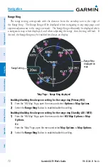
Page 94: ...yed and when adjusting the range then the ring will fade If desired the Range Ring may be enabled for always on display Map Page Range Ring displayed Range Ring displayed on map Range Setting Enabling disabling the always on setting for the range ring Primary HSI 1 From the HSI Map Page open the menu and select Options Map Options 2 Select the Range Ring Button to enable disable this setting Enabl...

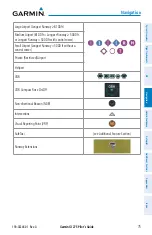
Page 95: ...ribe the various symbols which may be displayed The amount of symbols displayed on the map at one time depends on the range and detail level Land Symbols Item Symbol Highways and Roads Interstate Highway Freeway International Highway Freeway US Highway National Highway State Highway Local Highway Local Road Local Road N A Railroads Large City 200 000 Medium City 50 000 Small City 5 000 State Provi...

Page 96: ... Flight Restriction TFR Class B Airspace Altitude Label ceiling floor Class C Airspace Altitude Label ceiling floor Class D Airspace Altitude Label ceiling Class B Terminal Maneuvering Area and surrounding airways CL B TMA AWY Class C Airspace Control Area CL C CTA Class D Airspace Class A Airspace CL A D Restricted and Prohibited Areas Restricted Military Operations Areas MOA Military ADIZ Alert ...

Page 97: ...arge Airport Longest Runway 8100 ft Medium Airport 8100 ft Longest Runway 5000 ft or Longest Runway 5000 ft with control tower Small Airport Longest Runway 5000 ft without a control tower Private Restricted Airport Heliport VOR VOR Compass Rose On Off Non directional Beacon NDB Intersections Visual Reporting Point VRP SafeTaxi see Additional Feature Section Runway Extensions ...

Page 98: ...yed when aircraft GPS location is valid but heading is invalid and aircraft is stationary Top of Descent TOD Bottom of Descent BOD MAP DETAIL The map detail setting changes allows the pilot to progressively step through four levels of detail that can be displayed on the navigation map Decreasing the Map Detail Level decreases how many map items are displayed Item Detail Level 4 Most 3 2 1 Least Sm...

Page 99: ...Levels for Decluttering Changing the map detail setting Primary HSI 1 From the HSI Map Page open the menu and select Options Map Options 2 Select the Map Detail Button Select the button again as necessary to cycle through each level of detail and choose the desired setting Changing the map detail setting Standby ADI MFD 1 From the HSI Map Page open the menu and select HSI Map Options Map Options M...

Page 100: ...ed SafeTaxi information will also be displayed depending on map range and detail level NOTE Some map options may or may not be available depending on what external source is available to provide the necessary data Airspace Display settings for airspace on the HSI Map Page may be set to Off to remove airspace from being shown on the navigation map or All to display all airspace Airspace may also be...

Page 101: ...s are selected for display on the HSI Map the airway waypoints VORs NDBs and Intersections are also displayed Airways on the HSI Map Page High Altitude Airway Low Altitude Airway Enabling disabling the display of airways 1 From the HSI Map Page open the menu and select Options Map Options 2 Select the Airways Button Select the button again as necessary to cycle through each option and choose the d...

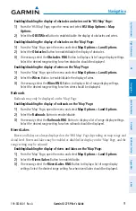
Page 102: ...abling disabling the display of relative terrain 1 From the HSI Map Page open the menu and select Options Map Options 2 Select the Terrain Button to enable disable the display of relative terrain on the map TFRs Temporary Flight Restrictions TFRs may be displayed on the HSI Map Page More information on TFRs is provided in the Hazard Avoidance Section Enabling disabling the display of TFRs 1 From t...

Page 103: ... traffic and traffic options see the Hazard Avoidance Section Enabling disabling the display of traffic 1 From the HSI Map Page open the menu and select Options Map Options 2 Select the Traffic Button to enable disable the display of traffic on the map Weather Legend A legend for weather products is available The legend will display information for each weather option that is enabled and displayed...

Page 104: ... Selecting the datalink weather source 1 From the HSI Map Page open the menu and select Options Map Options Weather Opts 2 Select the Datalink Weather Button to toggle between SiriusXM or FIS B NEXRAD The NEXRAD weather option will display NEXRAD precipitation data on the map See the Hazard Avoidance section for more information on NEXRAD data HSI Map Page NEXRAD displayed NEXRAD data Enabling dis...

Page 105: ...heliports may be displayed on the Map Page at the pilot s discretion by changing the display settings for private small medium and large airports Enabling disabling the display of Airports on the Map Page 1 From the Map Page open the menu and select Map Options Map Options Aviation Options 2 Select the Airports Button to enable disable the display of airports Changing display settings for each air...

Page 106: ...osing to only show airspace below a certain altitude For example if Below 3000FT is selected only airspace below 3000 feet will be depicted on the map This may result in only some rings of the Class B or Class C airspace being displayed if no portion of that ring extends below 3000 feet Changing the HSI Map Page airspace display settings 1 From the HSI Map Page open the menu and select HSI Map Opt...

Page 107: ...lect the Airspace Options Button b Select the Show Airspaces Button The option to display no airspace Off all airspace All or only airspace below a certain altitude is provided Select the desired Airspace Setting Button Changing Map Page display settings for each airspace type 1 From the Map Page open the menu and select Map Options Map Options Aviation Options Airspace Options 2 Select the desire...

Page 108: ...Smart Airspace function de emphasizes airspaces on the Map Page depending on the current aircraft altitude The function does not require the aircraft present position or flight path to enter the lateral boundaries of the airspace If the current aircraft altitude is within 1500 feet of the vertical boundaries of the airspace the airspace boundary is shown normally If the current aircraft altitude i...

Page 109: ...lect the Off All High or Low Button to display the desired airways Enabling disabling the display of airways on the Map Page 1 From the Map Page open the menu and select Map Options Aviation Options 2 Select the Airways Button and select the All High or Low Button to display the desired airways Or Select the Low Airways Button and the High Airways Button as necessary to enable disable the desired ...

Page 110: ...Enabling disabling AutoZoom on the Map Page 1 From the Map Page open the menu and select Map Options Map Options 2 Select the AutoZoom Button to enable disable the function Setting the minimum and maximum range for AutoZoom 1 From the Map Page open the menu and select Map Options Map Options 2 Select the AutoZoom Min Button Then select the button for the desired minimum range setting 3 Select the ...

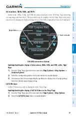
Page 111: ...B Intersections Options Touch to Enable Range Button Enabling disabling the display of Intersections NDBs VORs and VRPs on the Map Page 1 From the Map Page open the menu and select Map Options Map Options Aviation Options 2 Select the corresponding button for the desired item to enable disable 3 If necessary select the corresponding Range Button to display a list of range settings Select the desir...

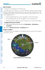
Page 112: ...ative to where the aircraft is going Track Up or to the current heading HDG UP North Up NORTH aligns the top of the map display to north default setting Track Up TRK aligns the top of the map display to the current ground track Heading Up HDG Up aligns the top of the map display to the current aircraft heading Changing the Map Page orientation 1 From the Map Page open the menu and select Map Optio...

Page 113: ... display of wires 3 If necessary select the Wires RNG Button to display a list of range display settings Select the desired range setting for when wires should be displayed Railroads Railroads may only be displayed on the Map Page Enabling disabling the display of railroads on the Map Page 1 From the Map Page open the menu and select Map Options Land Options 2 Select the Railroads Button to enable...

Page 114: ...r disabled for display on the Map Page and the range setting for each kind may be adjusted Road Options Enabled Range Button Adjusting the display of roads on the Map Page 1 From the Map Page open the menu and select Map Options Land Options 2 Select the Roads Button to enable disable the display of roads 3 Select the Road Options Button 4 Select the button for each desired road type to enable dis...

Page 115: ...isabling the display of runway extensions 1 From the Map Page open the menu and select Map Options Aviation Options 2 Select the Runway EXT Button to enable disable the display of runway extensions on the map 3 If necessary select the Runway EXT RNG Button to display a list of range settings Select the desired range display setting SafeTaxi If configured SafeTaxi information is always displayed on...

Page 116: ... when state borders should be displayed Track Vector The HSI Map Page and the Map Page can display a track vector that is useful in minimizing track angle error The track vector is a dashed cyan line segment extended to a predicted location The track vector look ahead time is selectable 30 sec 60 sec default 2 min 5 min 10 min 20 min and determines the length of the track vector Map Page Track Vec...

Page 117: ...g procedures Topographical Data Color Correlation Topographical Data and Color Correlation Topo Data displayed on map Enabling disabling the display of topographical data on the HSI Map Page 1 From the HSI Map Page open the menu and select HSI Map Options Map Options 2 Select the Topo Button to enable disable the display of topographical data from the map Enabling disabling the display of topograp...

Page 118: ...which overlays colors on the map depending on the aircraft altitude Map Page Terrain and Obstacles displayed Terrain Data displayed on map Terrain Overlay Icons Enabling disabling the display of relative terrain 1 From the HSI Map Page open the menu and select HSI Map Options Map Options Or From the Map Page open the menu and select Map Options 2 Select the Terrain Button to enable disable the dis...

Page 119: ...n on traffic data see the Hazard Avoidance Section Map Page Traffic displayed Traffic Data displayed on map Traffic Overlay Icon Enabling disabling the display of traffic for the HSI Map Page 1 From the HSI Map Page open the menu and select HSI Map Options Map Options 2 Select the Traffic Button to enable disable the display of traffic Enabling disabling the display of traffic for the Map Page 1 F...

Page 120: ...p Weather Legend A legend for weather products is available The legend will display information for each weather option that is enabled and displayed on the map For more information on how to display weather products on the map see the following Weather Options discussion Viewing the Weather Legend for the HSI Map Page 1 From the HSI Map Page open the menu and select Options Map Options 2 Select t...

Page 121: ...ning is available Enabling disabling the display of SiriusXM Lightning on the HSI Map Page 1 From the HSI Map Page open the menu and select HSI Map Options Map Options Weather Opts 2 Select the Lightning Button to enable disable the display of lightning on the map Enabling disabling the display of SiriusXM Lightning on the Map Page 1 From the Map Page open the menu and select Map Options Weather O...

Page 122: ...er Options 2 Select the NEXRAD Button to enable disable Enabling disabling the display of NEXRAD for the Map Page 1 From the Map Page open the menu and select Map Options Or From the Map Page open the menu and select Map Options Weather Options 2 Select the NEXRAD Button to enable disable Selecting the NEXRAD Source SiriusXM only for the HSI Map Page 1 From the HSI Map Page open the menu and selec...

Page 123: ...ormscope Mode Button as desired to toggle between Cell Mode or Strike Mode Enabling disabling the display of Stormscope for the Map Page 1 From the Map Page open the menu and select Map Options Weather Options 2 Select the Stormscope Button to enable disable the display of lightning data on the map 3 Select the Stormscope Mode Button as desired to toggle between Cell Mode or Strike Mode RESTORE DE...

Page 124: ...ce and airway information Map panning Airport waypoint selected Information Banner Selected map feature Map Feature Info Button Back Button Select to see other map features present Panning the map 1 From the Map Page select the map The crosshair is displayed indicating the map is in the panning mode 2 Touch and drag the map to pan 3 Touch the Back Button to exit map panning and re center the map o...

Page 125: ...tionscreen Seethefollowingtableforadescriptiononeachinformation screen that may be displayed Info VOR Screen Select arrows or swipe to scroll all information Distance Bearing Coordinates Location Frequency Nearest Airport VOR Class Station Declination Screen Information Airport General Info Screen Identifier Facility Name Airport Category Distance to airport from aircraft present position Bearing ...

Page 126: ...rom aircraft present position Bearing to NDB Lat Lon coordinates Location city state province country Frequency Nearest airport to NDB identifier distance bearing Marker Description Info VOR Screen Identifier Distance to VOR from aircraft present position Bearing to VOR Lat Lon coordinates Location city state province country Frequency Nearest airport to VOR identifier distance bearing VOR class S...

Page 127: ...N NAVIGATION WARNING Do not use GPS to navigate to any active waypoint identified as a NON WGS84 WPT by a system message NON WGS84 WPT waypoints are derived from an unknown map reference datum that may be incompatible with the map reference datum used by GPS known as WGS84 and may be positioned in error as displayed DIRECT TO NAVIGATION This portion of the guide will discuss the Direct To navigati...

Page 128: ...ports List Selecting a Direct To destination using the page menu 1 From any page open the menu 2 Select the Button The Direct To Screen is displayed 3 Select the Waypoint Button 4 Select the Recent Button A list of previously selected airports is displayed Select the desired Airport Selection Button Or Select the Nearest Button A list of airports is displayed in order of distance from aircraft pre...

Page 129: ...to activate the panning mode then pan the map as needed and touch the desired destination 2 Select the Button The Direct To Screen is displayed showing the selected destination waypoint and course information If the selected destination is not defined in the navigation database the system will create a MAPWPT 3 Select the Activate Button Removing a Direct To destination 1 From any page open the me...

Page 130: ...a for nearest Direct To airports 1 From any page open the menu Select System Setup Airport Criteria 2 Select the Runway Surface Button Then select the desired Surface Criteria Button 3 Select the Runway Length Button Enter the desired minimum runway length using the keypad and press the Enter Button FLIGHT PLAN DIRECT TO NAVIGATION FROM EXTERNAL SOURCE NOTE To receive flight plan data a compatible...

Page 131: ...vigation data will be displayed on maps using different line widths colors and types based on the type of leg and the segment of the flight plan currently being flown Direct to leg displayed on the Map Page Direct to Waypoint Direct to leg shown in magenta Flight plan displayed on the Map Page Flight plan information received from external source Active Leg Waypoint Active flight plan leg shown in...

Page 132: ...y over waypoints discussed later in this section A Roll Steering Path that is beyond the next leg will appear as a Future Roll Steering Path When a Future Roll Steering Path becomes the next leg it appears as a Roll Steering Path Procedures Loaded in a Flight Plan NOTE The system responds to terminal procedures based on data coded within that procedure in the Navigation Database Differences in sys...

Page 133: ...rack ETA Estimated time of arrival at active fix ETA at DEST ETA at Destination ETE Estimated time enroute at active fix ETE to DEST Estimated time enroute to destination GS Groundspeed GSL Geometric Sea Level Altitude MSA Minimum Safe Altitude OAT Static Outside Air Temperature OAT Total Outside Air Temperature TKE Track Angle Error TRK Track Time Current Time XTK Cross track error MFD Data Page ...

Page 134: ... are discussed in the System Overview Section of this guide See the pertinent flight manual of the external navigator for instructions on enabling the flight plan import function 4 4 ABNORMAL OPERATIONS ABNORMAL GPS CONDITIONS The annunciations in the following table may appear when abnormal GPS conditions occur GPS navigation will resume automatically once a valid GPS solution is restored Annunci...

Page 135: ...ackup GPS The VFR GPS is continuously being monitored and compared to the Primary GPS so that a seamless and automatic transition to the VFR GPS will be made if the Primary GPS fails If all configured external GPS sources fail the MFI will revert to using the internal VFR GPS for emergency Direct To navigation guidance and position data on the moving map In this case a system message is generated ...

Page 136: ...opilot Additional Features Appendices Index Complete Loss of GPS If a complete loss of GPS occurs the ownship icon is removed and the No GPS POS annunciation will be displayed in amber on the moving map TAWS terrain and SVT features will be lost and the CDI will be removed Complete Loss of GPS No GPS POS annunciation on HSI Map Page ...

Page 137: ...Collision Avoidance System TCAS Automatic Dependent Surveillance Broadcast ADS B Traffic 5 2 DATALINK WEATHER WARNING Do not use datalink weather information for maneuvering in near or around areas of hazardous weather Information contained within datalink weather products may not accurately depict current weather conditions WARNING Do not use the indicated datalink weather product age to determin...

Page 138: ... activation The Data ID Code may be found on the Datalink Status Page Viewing the Data ID Code 1 From the SXM WX Page open the page menu Select SXM WX Options Datalink Status 2 The Data ID is displayed at the top of the Datalink Status Page Activating SiriusXM Service 1 Contact SiriusXM using the customer service phone number listed on their website 2 Provide SiriusXM customer service the Data ID ...

Page 139: ...ata and delivers subscription free weather information periodically and automatically FIS B uses a network of FAA operated Ground Based Transceivers GBTs to transmit information Reception is limited to line of sight and is available below 24 000 feet MSL in the United States FIS B transmits weather data in a repeating cycle which may take several minutes to transmit all available weather data Ther...

Page 140: ...WEATHER PRODUCTS The following table shows each weather product and map symbol Availability of weather products depend on the datalink equipment and subscription service if applicable Weather Product Symbol METARs TAFs N A SIGMETs AIRMETs Pilot Weather Report PIREP Winds Aloft Temporary Flight Restriction TFR Radar Precipitation NEXRAD US Regional Lightning Cloud Top Echo Top Cell Movement ...

Page 141: ... METARs and TAFs NOTE METAR information is only displayed within the installed aviation database service area METAR METeorological Aerodrome Report is an international code used for reporting weather observations METARs are updated hourly or as needed METARs typically contain information about the temperature dew point wind precipitation cloud cover cloud heights visibility and barometric pressure...

Page 142: ...ed by the METAR The text from a METAR or TAF can be displayed by touching the flag on the weather page and then selecting the Info Button METAR Symbols VFR Ceiling greater than 3 000 ft AGL and visibility greater than five miles Marginal VFR Ceiling 1 000 to 3 000 ft AGL and or visibility three to five miles IFR Ceiling 500 to 1 000 ft AGL and or visibility one to three miles Low IFR Ceiling below...

Page 143: ...lence including vertical extent IFR Weather conditions with ceilings 1 000 ft and or visibility 3 mi MTN OBSR Widespread mountain obscuration due to clouds precipitation smoke haze mist or fog Surface Winds Sustained surface winds 30 kt and or potential non convective wind shear below 2 000 ft AGL SIGMETs A SIGMET SIGnificant METeorological Information advises of weather that is potentially hazard...

Page 144: ...ed as either Routine UA blue or Urgent UUA yellow Selected PIREP on SXM WX Page Selected PIREP Touch to display PIREP text Range Touch to display Time Stamp information Winds Aloft Winds Aloft data shows the forecasted wind speed and direction at the surface and at selected altitudes Altitudes can be displayed in 3 000 ft increments up to 42 000 feet MSL Winds Aloft are displayed using wind barbs ...

Page 145: ...A 123 Hazard Avoidance System Overview Flight Instruments EIS Navigation Hazard Avoidance Autopilot Additional Features Appendices Index Winds Aloft displayed on the SXM WX Page Wind Barb Range Displayed Weather Altitude Setting Wind Barb Symbols ...

Page 146: ...ion Always confirmTFR information through official sources such as Flight Service Stations or Air Traffic Control Temporary Flight Restrictions TFRs temporarily restrict all aircraft from entering the selected airspace unless a waiver has been issued TFRs are routinely issued for activities such as sporting events dignitary visits military depots and forest fires TFRs are represented as an area ou...

Page 147: ...ather severity level The display of radar coverage is always active when NEXRAD is selected Areas where NEXRAD radar coverage is not currently available or is not being collected will be depicted as No Radar Coverage until coverage is restored There are possible abnormalities regarding displayed NEXRAD images Some but not all of those include Ground clutter Strobes and spurious radar data Sun stro...

Page 148: ... instance wet hail returns a strong radar reflection while dry hail does not Both wet and dry hail can be extremely hazardous Colors are used to identify the different NEXRAD echo intensities reflectivity measured in dBZ decibels of Z Reflectivity designated by the letter Z is the amount of transmitted power returned to the radar receiver The dBZ values increase as returned signal strength increas...

Page 149: ...Displays high resolution weather image of current region CONUS Displays low resolution weather image of the continental US Combined Display of both Regional and CONUS imagery Lightning SiriusXM Lightning data shows the approximate location of cloud to ground lightning strikes A strike icon represents at least one strike that has occurred within a two kilometer region and within the last seven minu...

Page 150: ...on The Cloud Tops weather product depicts cloud top altitudes as determined from satellite imagery Cloud top altitude is provided in the Information Banner displayed at the top of the screen when panning the SXM WX Page Cloud Tops Legend and Display Cloud Tops Altitude Pan the map to display Cloud Tops Altitude Cell Movement SiriusXM The Cell Movement weather product displays the location and proj...

Page 151: ...els SiriusXM The Freezing Level weather product shows the color coded contour lines for the altitude and location at which the freezing level isotherm is found When no data is displayed for a given altitude the data for that altitude has not been received or is out of date and has been removed from the display New data appears when it becomes available Freezing Levels on SXM WX Page Freezing Level...

Page 152: ...epresentation of the current conditions at the time of the analysis as determined by a computer model Supercooled Large Droplet SLD icing conditions are characterized by the presence of relatively large super cooled water droplets indicative of freezing drizzle and freezing rain aloft SLD threat areas are depicted over the CIP colors Icing Legend County Warnings SiriusXM The County Warnings weathe...

Page 153: ...urrent location of cyclones hurricanes tropical storms and their projected tracks The system displays projected track information in the form of DD HH MM Cyclone projected path on SXM WX Page Cyclone Path Surface Analysis and City Forecast SiriusXM Surface Analysis and City Forecast information is available for current and forecast weather conditions Forecasts are available for intervals of 12 24 ...

Page 154: ...ices Index City Forecast Symbols Turbulence SiriusXM The Turbulence weather product identifies the potential for erratic movement of high altitude air mass associated winds Turbulence is classified as light moderate severe or extreme at altitudes between 21 000 ft and 45 000 ft Turbulence information is intended to supplement AIRMETs SIGMETs and PIREPs Turbulence Legend ...

Page 155: ...M and FIS B weather products are broadcast automatically on a repeating cycle without pilot intervention Each datalink weather product has an expiration time The weather product age is shown in white if it is less than half of this expiration time otherwise it is shown in amber until reaching its expiration time After a weather product has expired the system removes the expired weather product and...

Page 156: ...yed at the bottom of the weather page See the table below for the different icons which may be displayed on the Time Stamps Button Select the Time Stamps Button to display information about each weather product and product age Time Stamp Symbols All selected weather products are considered current Product ages are newer than half the expiration times One or more weather product is considered stale...

Page 157: ...ion of the Navigation Section for more information on weather overlay options for other map pages Each weather product listed in the page options menu may be enabled or disabled for display The annunciator bar on the button will be green when an item is enabled for display Some weather products may have other settings available for selection A Legend of weather products is also available The displ...

Page 158: ...ather Product Button The weather product is enabled for display when the annunciator bar is green 3 Scroll the list as necessary and select each Weather Product Button to enable disable as desired Displaying information for a selected weather product 1 Select the SXM WX Page Or Select the FIS B WX Page 2 Touch the desired weather product icon Or Touch and drag to pan to the location of the desired...

Page 159: ...ing Changing the AIRMET settings 1 From the SXM WX Page open the page menu and select SXM WX Options Layers Or From the FIS B WX Page open the page menu and select FIS B WX Options Layers 2 Select the AIRMET Settings Button to display the AIRMET Setup Screen 3 Scroll the list as necessary and select each AIRMET Type Button to enable disable as desired Changing the county warnings settings 1 From t...

Page 160: ...ng strikes and cells based on the age of the information Lightning Age Symbol Strike is less than 6 seconds old Strike is between 6 and 60 seconds old Strike is between 1 and 2 minutes old Strike is between 2 and 3 minutes old Lightning Age and Symbols STORMSCOPE OPTIONS NOTE When using Stormscope there are several atmospheric phenomena in addition to nearby thunderstorms that can cause isolated d...

Page 161: ...ng Page Orientation Strikes 360 View Display Mode Range Rate displays number of strikes per minute Selecting the Stormscope view 1 From the Lightning Page open the page menu and select Lightning Opts 2 Select the View Button to toggle between 360 and Arc Selecting the Stormscope mode 1 From the Lightning Page open the page menu and select Lightning Opts 2 Select the Mode Button to toggle between C...

Page 162: ... the system s ability to process the data representing the affected areas NOTE No terrain or obstacle alerting occurs if Terrain Proximity is the only terrain function configured The following terrain configurations are allowed Terrain Function Description Terrain Proximity Displays relative terrain and obstacle data Terrain FLTA Displays relative terrain and obstacle data and provides aural and v...

Page 163: ...er setting for local atmospheric conditions The most accurate baro corrected altitude can be achieved by frequently updating the altimeter setting to the nearest reporting station along the flight path However because actual atmospheric conditions seldom match the standard conditions defined by the International Standard Atmosphere ISA model where pressure temperature and lapse rates have fixed va...

Page 164: ...acle Lighted Obstacle Obstacle Location 1000 AGL 1000 AGL 1000 AGL 1000 AGL Red obstacle is above or within 100 ft below the aircraft altitude Yellow obstacle is between 100 ft and 1000 ft below the aircraft altitude White obstacle is more than 1000 ft below aircraft altitude Relative Obstacle Symbols and Colors Wire Obstacle Wire Obstacle Location Red wire obstacle is above or within 100 ft below...

Page 165: ...rmation can be displayed on the Map Page and the HSI Map Page When terrain and or obstacle data is overlaid on maps an icon is displayed for each type of feature enabled for display depending on the current range setting For more information on terrain overlay options on map pages and which unit configurations offer map pages see the Map Options discussion in the Navigation Section If configured a...

Page 166: ...le data is overlaid on maps other than the Terrain Page an icon is displayed for each type of feature enabled for display depending on the current range setting Terrain information can be overlaid independently of obstacle data however obstacles identified by Terrain Proximity as yellow or red are shown when terrain is selected for display and the map range is within the setting limit Additional i...

Page 167: ...egend TERRAIN ALERTS Alerts are issued when flight conditions meet parameters that are set by the configured terrain function Terrain alerts typically employ a CAUTION or a WARNING alert severity level or both When an alert is issued visual annunciations are displayed Forward Looking Terrain Avoidance FLTA compares the projected flight path as derived from GPS data with terrain features and obstac...

Page 168: ... and Primary HSI When a threat is detected terrain obstacle or wire a TER annunciation will be displayed on each page This annunciation will flash for five seconds before being displayed steady until the threat is cleared Both caution and warning annunciations may be displayed Primary ADI and Primary HSI Terrain Alert Examples Terrain Warning on Primary HSI Terrain Caution on Primary ADI In additi...

Page 169: ...e Wire Impact Caution Caution Terrain Obstacle Wire Terrain Obstacle Wire Premature Descent Alert Caution Aural alert provided by the external TAWS B System Primary ADI and Primary HSI Terrain Annunciations Terrain Alerts Standby ADI Standby HSI and MFD When a threat is detected a pop up alert is displayed when viewing any page other than the Terrain Page An annunciation is also displayed on the b...

Page 170: ...ain Warning Annunciation Obstacle Caution Pop Up Threat Indicator Terrain Page Wire Caution Obstacle Caution Annunciation In addition to the pop up alert and or alert annunciation the MFI may also give aural alerts the Terrain Proximity function does not provide aural alerts If an external TAWS B system is configured aural alerts may be provided by the external system NOTE Only visual annunciation...

Page 171: ...ire TER TERRAIN Or OBSTACLE Or WIRE Imminent Terrain Obstacle Wire Impact Caution Caution Terrain Obstacle Wire Terrain Obstacle Wire Premature Descent Alert Caution TERRAIN Aural alert provided by the external TAWS B System Standby ADI and MFD Terrain Annunciations TERRAIN INHIBIT Terrain alerts may be manually inhibited Doing so will deactivate all aural and visual annunciations associated with ...

Page 172: ... status annunciations and conditions that may occur Alert Type Aural Alert Annunciations All Pages Annunciations Terrain Page Terrain test in progress None TER TER TEST Terrain alerting inhibited None TER INHB No GPS position Terrain System Not Available TER TER N A Excessively degraded GPS signal or out of database coverage area Terrain System Not Available TER N A Terrain test fail Terrain or Ob...

Page 173: ...raffic avoidance maneuvers are based upon Traffic ResolutionAdvisories ATC guidance or positive visual acquisition of conflicting traffic NOTE Only visual annunciations will be provided on the MFI for traffic alerts For information on traffic voice alerts see the pertinent flight manual for each configured traffic system Collision avoidance and traffic surveillance data may be displayed on the Tra...

Page 174: ... to the aircraft s current position and altitude can be displayed Orientation on this page is always heading up unless there is no valid heading The range may be adjusted by selecting the Range Button and using the Inner Knob to zoom in or out Traffic source and mode information will be displayed on the outer edge of the display on the Traffic Page The following table lists the different informati...

Page 175: ...splays non threat and proximity traffic from 2700 feet above the aircraft to 2700 feet below the aircraft typically used during enroute phase of flight Above Displays non threat and proximity traffic from 9000 feet above the aircraft to 2700 feet below the aircraft typically used during climb phase of flight Below Displays non threat and proximity traffic from 2700 feet above the aircraft to 9000 ...

Page 176: ...y be displayed on the Traffic Page with ADS B traffic source configured More information on ADS B traffic is discussed later in this section Selected target on Traffic Page with TCAS Information Banner Range Traffic Status Annunciations Target Highlighted Traffic Advisories Viewing traffic target information Touch the desired target symbol on the Traffic Page Information about the selected target ...

Page 177: ...ons see the Map Options portion of the Navigation Section System Status Traffic Icon Operating No Traffic Data Available Traffic Status Icon on map displays Traffic Alerts Primary ADI and Primary HSI A Traffic Alert TA may be issued anytime there is an increase in the number of traffic advisories Traffic advisory parameters and alerts depend on the traffic source configuration in use When a traffi...

Page 178: ... be displayed on every page To acknowledge a traffic pop up alert Touch the Close Button returns to the currently viewed page or Touch the Go to Traffic Button accesses the Traffic Page Traffic Pop up Alert on the Map Page Traffic Pop up Alert Touch to go to the Traffic Page Traffic Page Advisories Traffic Advisory information is provided on the Traffic Page See the following table for a list of t...

Page 179: ...MVD Traffic is removed because it is too old for coasting 12 to 60 seconds since last message Traffic may exist within the selected display range but it is not displayed TRFC FAIL Traffic data has failed TRFC UNAVAIL The traffic service is unavailable or out of range Traffic Advisory Information on the Traffic Page If the traffic source fails information as to the cause of the failure is shown in ...

Page 180: ...DS B traffic can be used in conjunction with TCAS and TAS Traffic Information Service TIS is designed to help in detection and avoidance of other aircraft TIS uses the Mode S transponder for the traffic datalink TIS receives traffic information from ground stations and is updated every 5 seconds The system displays up to eight traffic targets within a 7 5 nm radius from 3000 feet below to 3500 fee...

Page 181: ...raft the TRAFFIC alert annunciation is generated only when the number of TAs increases For example when the first TA is displayed an annunciation is generated As long as a single TA remains on the display no additional alerts are generated If a second TA appears on the display or if the number of TAs initially decreases and then subsequently increases another alert is generated The annunciation UN...

Page 182: ...ft Due to lack of equipment poor signal reception and or inaccurate information from other aircraft traffic may be present but not represented on the display NOTE If equipped ADS B Traffic can be shared with certain Bluetooth connected devices Refer to System Overview Section for Bluetooth pairing instructions Automatic Dependent Surveillance Broadcast ADS B is a core technology in the FAA NextGen...

Page 183: ...uencies 1090 MHz and 978 MHz Both frequencies provide the same traffic information An aircraft may be ADS B In Out or participating on one or both frequencies depending on the installed equipment The 1090 MHz frequency portion of ADS B is known as 1090 Extended Squitter 1090 ES The 978 MHz portion of ADS B is known as Universal Access Transceiver UAT Because it is not required that ADS B In capabl...

Page 184: ...tion coverage in SSR coverage and the other aircraft is also in SSR coverage and is transmitting its altitude The ground station provides ATC radar information for other aircraft within 3 500 feet and 15 NM of the participant to include altitude position ground speed and ground track TIS B broadcasts occur once every three to thirteen seconds depending on the characteristics of the ground station ...

Page 185: ...on the ground ADS B Traffic Symbology The display settings motion and duration for motion vectors may be accessed through the traffic options menu The display of motion vectors may also be turned off Changing motion vector display settings 1 From the Traffic Page open the page menu and select Traffic Options 2 Select either the Motion Vector Button or the Vector Duration Button to display more set...

Page 186: ...ns supported by the MFI Airborne Situational Awareness AIRB and Surface Situational Awareness SURF and ADS B Traffic Advisory System ATAS AIRB is considered the fundamental airborne traffic application ATAS provides alerts when airborne traffic trajectories pose a potential collision risk SURF provides additional situational awareness when on ground or within the terminal environment The system au...

Page 187: ... TEST is displayed next to the Traffic Source on the Traffic Page Traffic information is provided in the information banner at the top of the Traffic Page Traffic information is dependent on the traffic source configuration The following lists the various kinds of data which can be displayed on the Traffic Page Registration call sign Vehicle type Closure Rate Track Ground Speed Traffic Page with A...

Page 188: ...sion Avoidance System TCAS I may be configured for use Differences between these traffic systems will be noted where applicable throughout this section TAS and TCAS enhance flight crew situational awareness by displaying traffic information for transponder equipped aircraft while also providing visual annunciations and alerts to assist the pilot in visually acquiring traffic When the traffic syste...

Page 189: ...eria Traffic Advisory Off Scale Traffic Symbol Description Relative altitude when available is displayed above or below the corresponding intruder symbol in hundreds of feet When this altitude is above own aircraft it is preceded by a symbol a minus sign indicates traffic is below own aircraft The system displays the altitude vertical trend as an up down arrow for speeds vertical greater than 500 ...

Page 190: ...vertical and horizontal separation Or Intruder closing rate provides less than 20 seconds of horizontal separation and vertical separation is within 600 feet Or Intruder range is within 0 2 nm and vertical separation is within 600 feet A No Intruder closing rate provides less than 15 seconds of separation B Yes Intruder closing rate provides less than 30 seconds of vertical and horizontal separati...

Page 191: ...es ten seconds to complete When the system test is initiated a test pattern of traffic symbols appears on the Traffic Page When the system test is complete the traffic system enters Standby Mode Standby mode will be indicated white in the center of the Traffic Page Otherwise the status of the traffic system will be indicated in the Traffic Source field on the Traffic Page Manually initiating syste...

Page 192: ...Garmin GI 275 Pilot s Guide 190 02246 01 Rev A 170 Hazard Avoidance System Overview Flight Instruments EIS Navigation Hazard Avoidance Autopilot Additional Features Appendices Index Blank Page ...

Page 193: ...w Damper control The Yaw Damper reduces Dutch Roll tendencies and coordinates turns It can operate independent of the Autopilot and may be used during normal hand flown maneuvers Yaw rate commands are limited by the Yaw Damper NOTE An external Flight Director AFCS Controller is required to fully operate the Autopilot capabilities of the MFI To utilize the Autopilot functionality the following hard...

Page 194: ...ands the pitch trim actuator to reduce the average pitch servo effort When the Autopilot is not engaged manual trim functionality is available at any time by using the Trim Switches ROLL AXIS The Autopilot roll axis uses roll rate to stabilize aircraft roll attitude during upsets and Flight Director maneuvers The Flight Director roll commands are rate and attitude limited combined with roll damper...

Page 195: ... cueing ENGAGING THE AUTOPILOT When the Autopilot is engaged via an external controller the Autopilot is activated on the MFI and is indicated by the magenta Command Bars and the amber Aircraft Symbol moving together in unison Engagement is also observed by indications on your external Flight Director or external controller Autopilot Engaged Command Bars and Aircraft Symbol Linked Together DISENGA...

Page 196: ...loss of ADC and GPS Invalid sensor data e g sensor mis compare or non compare NOTE During system startup if the Autopilot is engaged though not typical the MFI will automatically disengage the Autopilot when the sensors initiate alignment NOTE In the event of an in flight restart the Autopilot may disengage Discrete Configurations The MFI can be configured to have airspeed discrete inputs tied to ...

Page 197: ...ion establishes a real time data transfer of flight information from the aircraft to the D2 Pilot Watch The optional Synthetic Vision Technology SVT depicts a forward looking attitude display of the terrain and traffic immediately in front of the aircraft on the ADI Page 7 2 SAFETAXI WARNING Do not use SafeTaxi information as the primary method of flight guidance during ground operations SafeTaxi ...

Page 198: ...en obstacles are displayed on the Navigation Map in the vicinity of an airport being viewed with SafeTaxi the obstacle symbols may be obscured by SafeTaxi feature labels Designated Hot Spots are recognized at airports with many intersecting taxiways and runways and or complex ramp areas Airport Hot Spots are outlined to caution pilots of areas on an airport surface where positional awareness confu...

Page 199: ...n Options SafeTaxi A subdued indication on the SafeTaxi Button indicates the feature is disabled A green indication signifies the feature is enabled Or 1 From the HSI Map Page or the Map Page open the menu and select HSI Map Options Map Options Map Options Map Detail 2 Select the lowest level of map detail 7 3 RADAR ALTIMETER OPTIONAL OVERVIEW The optional Radar Altimeter Rad Alt display on the MF...

Page 200: ...Airborne Radar Altimeter Digital Rad Alt Indicator DH Set to 200 Analog Altitude Scale DH Bug Indicator Needle Setting the Radar Altimeter Decision Height DH From the Rad Alt Page turn the Inner Knob to increase or decrease the DH Or 1 From the Rad Alt Page touch the DH Button 2 Enter the desired height using the numeric keypad 3 Touch the Enter Button When the aircraft is airborne and descends th...

Page 201: ...o run the Rad Alt Test NOTE The Radar Altimeter Test is only available while on the ground This purpose of this feature is to test the communication between the MFI and an external radar altimeter Refer to the hardware s pertinent manual for external radar altimeter hardware testing During the test the annunciation RA TEST is present and a predetermined height is displayed e g 50 If the test fails...

Page 202: ...he power is applied to the system WIRELESS FLIGHT DATA LOGGING WITH CONNEXT For registration and connection instructions see the applicable sections in System Overview Wireless Flight Data Logging is enabled through Garmin Pilot and utilizes Connext The Flight Data Log is attached to your logbook entry and saved to flygarmin com for future analysis While Garmin Pilot is running the Flight Data Log...

Page 203: ...ck of the MFI The following alert prompts the pilot 2 Touch the Yes Button to take you to the USB Page USB Screen 3 Select Export Aircraft Report or Export Flight Data Logs The MFI begins the export process The export is complete when the MFI displays Complete 100 00 All flight data logged on a specific date is stored in a file named in a format which includes the date time and nearest airport ide...

Page 204: ... R L Ctr gals Aux Fuel Qty 1 2 Baro Altitude ft Pitch Roll deg Indicated Airspeed kts True Airspeed knots OAT deg C Pressure Altitude ft Altimeter Setting in Hg GPS altitude WGS84 datum Vertical Speed fpm Vertical Speed Selected fpm Ground Speed kts Ground Track deg mag Magnetic Heading deg Magnetic Variation deg HSI Sel GPS 1 2 NAV 1 2 Selected Course deg CDI deflection Nav 1 Nav 2 Frequency Com1...

Page 205: ...ic and Total Height Above Terrain HAT Density Altitude The D2 Watch must be paired with the MFI in order to use the various functions Pairing is accomplished once for each device After the initial pairing with Auto Reconnect enabled your D2 Watch will automatically reconnect with the MFI The pairing operation is completed from the D2 Watch and the MFI The MFI can connect three Bluetooth devices an...

Page 206: ...connection on the MFI Viewing connected devices 1 Open the menu and select System Wireless 2 Scroll down and select Bluetooth Devices 3 A list of devices is displayed on the next screen Select your connected device See the following image 4 In the following example the watch s name is D2 Delta S and its status is Online Additionally note the connected devices MAC Address Use this information to co...

Page 207: ...ct the Auto Reconnect Button to disable the automatic reconnection functionality green annunciator is not illuminated Removing a paired device 1 Open the menu and select System Wireless Bluetooth Devices 2 A list of devices is displayed on the next screen Select your connected D2 Watch 3 Scroll down and select the Remove Device Button to remove the selected D2 Watch from the MFI 7 6 SYNTHETIC VISI...

Page 208: ...ayed pitch range on the attitude indicator changes based on whether SVT is displayed The depicted imagery is derived from the aircraft attitude heading GPS three dimensional position and a 9 9 arc second database of terrain obstacles and other relevant features SVT will not display without a valid GPS position The terrain data resolution of 9 9 arc seconds meaning that terrain elevation contours a...

Page 209: ...rain or obstacles Displayed terrain or obstacles in the aircraft s flight path extending above the FPM could indicate a potential conflict even before an alert is issued by TAWS Terrain FLTA However decisions regarding terrain and or obstacle avoidance should not be made using only the FPM Zero Pitch Line The Zero Pitch Line is drawn completely across the ADI and represents the horizon when the te...

Page 210: ...ion on the synthetic terrain display When activated the signs appear on the display when the aircraft is approximately 15 nm from an airport and disappear at approximately 4 5 nm Airport signs are shown without the identifier until the aircraft is approximately 8 nm from the airport Airport signs are not shown behind the airspeed or altitude display Activating and deactivating Airport Signs 1 From...

Page 211: ... runways Runway data provides improved awareness of runway location with respect to the surrounding terrain All runway thresholds are depicted at their respective elevations as defined in the database In some situations where threshold elevations differ significantly crossing runways may appear to be layered As runways are displayed those within 45 degrees of the aircraft heading are displayed in ...

Page 212: ...a terrain or obstacle alert may be issued with no conflict shading displayed on the synthetic terrain In these cases the conflict is outside the SVT field of view to the left or right of the aircraft Obstacles are represented on the synthetic terrain display by standard two dimensional tower or wind turbine symbols found on the navigation maps and charts Obstacle symbols appear in the perspective ...

Page 213: ...ls and coloring are consistent with that used for traffic displayed on the navigation or traffic maps If the traffic altitude is unknown the traffic will not be displayed on the SVT display For more details refer to the traffic discussion in the Hazard Avoidance Section SVT TROUBLESHOOTING Garmin SVT is intended to be used with traditional attitude heading obstacle terrain and traffic inputs SVT i...

Page 214: ...Garmin GI 275 Pilot s Guide 190 02246 01 Rev A 192 Additional Features System Overview Flight Instruments EIS Navigation Hazard Avoidance Autopilot Additional Features Appendices Index Blank Page ...

Page 215: ... failed a red or amber X may be displayed The instrument may also issue audio alert tones or voice alerts when specific conditions are met For function specific aural alerts see the function s corresponding section of this guide for more information EIS Alerts are displayed in the Annunciation Banner on all EIS Pages For more information on EIS Alerts see the EIS Alerts discussion in the EIS Secti...

Page 216: ...w Flight Instruments EIS Navigation Hazard Avoidance Autopilot Additional Features Appendices Index Example Pop Up Alert Traffic Pop up Alert TRAFFIC Annunciation Caution Alert Level Example of Failure Annunciations Red or Amber X Annunciation Indicates System Component Failure ...

Page 217: ...from one or more units is not within tolerances of the other ADC units ADC 1 2 3 MISSING Or ADC MISSING ADC data from one or more units is missing ADS traffic alerting inoperative ADS B LRU reports CSA TSAA failure ADS traffic function inoperative The ADS B LRU reports a traffic alerting failure ADS B In traffic source mismatch Unit has received ADS B traffic from a source other than the configure...

Page 218: ... Database SYNC in progress Database synchronization is in progress view Status Page for more information EGT Difference Pilot specified EGT difference is exceeded by one or more engines GMC ESP inoperative GMC Electronic Stability Protection has failed GPS 1 2 inoperative The indicated GPS source failed or input data not received High BAT voltage Pilot defined engine advisory limitation exceeded H...

Page 219: ...tive yet Database is not yet active Obstacle database expired Database is expiring imminently or has expired Obstacle database not effective yet Database is not yet active System is in Battery Mode System is operating in battery mode SafeTaxi database expired Database is expiring imminently or has expired SafeTaxi database not effective yet Database is not yet active Service required The system or...

Page 220: ...erage Outside of SVT Terrain database coverage area SVT not available due to databases SafeTaxi or Basemap database corrupted or unavailable on ADI SVT successfully enabled SVT feature has been enabled in this power cycle SVT Trial 1 hour remaining Less than 1 hour of SVT trial remains SVT Trial 5 hours remaining 1 5 Hours of SVT Trial remain TAS TCAS function inoperative TAS TCAS device reports t...

Page 221: ... electrical fault calibration data fault SW CRC Fault or FPGA CRC Fault Communication is lost with UAT receiver capable ADS B LRU UAT fault The UAT LRU reports a low battery or fan fault UAT traffic data receiver fault The ADS B LRU reports that it is unable to receive UAT traffic and FIS B data USB and WiFi Unavailable While on internal battery operation the unit conserves energy by disabling the...

Page 222: ...Garmin GI 275 Pilot s Guide 190 02246 01 Rev A 200 Appendix A System Overview Flight Instruments EIS Navigation Hazard Avoidance Autopilot Additional Features Appendices Index Blank Page ...

Page 223: ...al Airspace System Garmin equipment will only recognize and use databases that are obtained from Garmin or Jeppesen Databases obtained from Garmin or Jeppesen that have a Type 2 Letter of Authorization LOA from the FAA are assured compliance with all data quality requirements DQRs A copy of the Type 2 LOA is available for each applicable database and can be viewed at flygarmin com by selecting Avi...

Page 224: ...ase are available every 28 days online flygarmin com There are two navigation database products available the Garmin Navigation Database or the Jeppesen Navigation Database which is sourced by Jeppesen NOTE Although the Jeppesen Navigation Database and the Garmin Navigation Database contain much of the same information pilots may notice differences in behavior nearest list functionality direct to ...

Page 225: ...gged directly into your computer and not into a USB hub computer screen or keyboard Database update fails Restart the MFI and retry the update Download the databases again Ensure the databases were purchased for the system ID of the MFI the database card is being used to update Database SYNC fails Ensure the databases were purchased for the MFI and all interfacing equipment configured for the MFI ...

Page 226: ...Garmin GI 275 Pilot s Guide 190 02246 01 Rev A 204 Appendix B System Overview Flight Instruments EIS Navigation Hazard Avoidance Autopilot Additional Features Appendices Index Blank Page ...

Page 227: ... Surveillance Rebroadcast AEA Aircraft Electronic Association AF Arc to Fix Leg AFCS Automatic Flight Control System AFM Airplane Flight Manual AFN ATS Facilities Notification AFMS Airplane Flight Manual Supplement AFRM Airframe AGL Above Ground Level AHRS Attitude and Heading Reference System AIM Aeronautical Information Manual AIRB Airborne AIRMET Airman s Meteorological Information AIRREP Air R...

Page 228: ...rving System B Both Runways B ALT Barometric Altitude BARO Barometer Barometric BATT Battery BC Backcourse Bearing The compass direction from the present position to a destination waypoint BFO Beat Frequency Oscillator BKSP Backspace Bluetooth Wireless standard for data exchange over short distances BOC Bottom of Climb BOD Bottom of Descent BRG see also Bearing C Degrees Celsius C Center Runway CA...

Page 229: ...G Cockpit Reference Guide CRNT Current Crosstrack Error The distance the aircraft is off a desired course in either direction left or right CRS see also Course Course to Steer CRSR Cursor CSA Conflict Situational Awareness CSC Current Speed Control CTA Control Area CTR Center CTRL Control Cumulative CUM The total of all legs in a flight plan CVDR Cockpit Voice Data Recorder CVR Cockpit Voice Recor...

Page 230: ...Go Remaining distance to last active FPL waypoint DTK see also Desired Track DQR Data Quality Requirements E Empty East EAS Engine and Airframe Systems ECU Engine Control Unit EDM Emergency Descent Mode EFC Expected Further Clearance Efficiency A measure of fuel consumption expressed in distance per unit of fuel EGNOS European Geostationary Navigation Overlay Service EGT Exhaust Gas Temperature EI...

Page 231: ...ed Time of Arrival ETE See also Estimated Time Enroute EVS Enhanced Vision System EXPIRD Expired F Degrees Fahrenheit FA Course From Fix to Altitude Leg FAA Federal Aviation Administration FADEC Full Authority Digital Engine Control FAF Final Approach Fix FAIL Failure FANS Future Air Navigation System FAR Federal Aviation Regulations FBO Fixed Base Operator FC Course From Fix to Distance Leg FCC F...

Page 232: ...ta Link GDR Garmin Data Radio GDU Garmin Display Unit GEA Garmin Engine Airframe Unit GEN Generator GEO Geographic GFC Garmin Flight Control GIA Garmin Integrated Avionics Unit GLONASS Global Orbiting Navigation Satellite Landing System GLS Global Navigation Satellite Landing System GMA Garmin Audio Panel System GMC Garmin Mode Controller GMT Greenwich Mean Time GMU Garmin Magnetometer Unit GND Gr...

Page 233: ...id Navigation System Horizontal Figure of Merit A measure of the uncertainty in the aircraft s horizontal position HOV Hover HOV P Hover Prediction hPa Hectopascal HPI Hover Power Indicator HPL Horizontal Protection Level HR Hour HRZN HDG Horizon Heading HSDB High Speed Data Bus HSI Horizontal Situation Indicator HT Heat HUL Horizontal Uncertainty Level Hz Hertz cycles per second I Inner Marker IA...

Page 234: ...quid Crystal Display LCL Local LDA Landing Distance Available LDG ETA at Final Destination LED Light Emitting Diode Left Over Fuel On Board The amount of fuel remaining on board after the completion of one or more legs of a flight plan or direct to Left Over Fuel Reserve The amount of flight time remaining based on the amount of fuel on board after the completion of one or more legs of a flight pl...

Page 235: ...isplay MGRS Military Grid Reference System MGT Measured Gas Temperature MHz Megahertz MIC Microphone MIN Minimum Minimum Safe Altitude MSA Uses Grid MORAs to determine a safe altitude within ten miles of the aircraft present position MKR Marker Beacon MOA Military Operations Area MON Monitor MOV Movement MORA Minimum Off Route Altitude MPEL Maximum Permissible Exposure Level MPM Meters per Minute ...

Page 236: ...IT PTCH Pitch POA Plain Old ACARS POH Pilot s Operating Handbook POHS Pilot s Operating Handbook Supplement POS POSN Position PPH Pounds per Hour PPM Parts per Million P POS Present Position PRES PRESS Pressure PROC Procedure s Procedure Turn PROP Propeller PROX Proximity PSI Pounds per Square Inch Power Situation Indicator PT Procedure Turn PTK Parallel Track PTT Push to Talk PWR Power Q Engine T...

Page 237: ...rtical Separation Minimums RX Receive S South SA Selective Availability SAR Search and Rescue SAT Static Air Temperature SBAS Satellite Based Augmentation System SCIT Storm Cell Identification and Tracking SD Secure Digital SEC Second s SEL SLCT Select SELCAL Selective Calling SENS Sense SFC Surface SIAP Standard Instrument Approach Procedures SID Standard Instrument Departure SIG AIR SIGMET AIRME...

Page 238: ...etween Two Fixes Leg TFR Temporary Flight Restriction TGT Target T HDG True Heading TIS Traffic Information Service TIS B Traffic Information Service Broadcast TIT Turbine Inlet Temperature TKE See also Track Angle Error TMA Terminal Maneuvering Area TMR REF Timer Reference TOC Top of Climb TOD Top of Descent Time to TOD TOGA TO GA Take Off Go Around TOLD Takeoff and Landing Data TOPO Topographic ...

Page 239: ...nding Speed VSB Maximum Speedbrake Speed VSR Stall Speed VT Takeoff Flap Retraction Speed VTIRE Maximum Tire Speed VX Best Angle of Climb Speed VY Best Rate of Climb Speed VYSE Best Single Engine Rate of Climb Speed V DEV Vertical Deviation VA Heading Vector to Altitude Leg VAC Volts Alternating Current VAPP VOR Approach VAR Variation VD Heading Vector to DME Distance Leg VDC Volts Direct Current ...

Page 240: ...RP Visual Reporting Point VS Vertical Speed VSD Vertical Situation Display VSI Vertical Speed Indicator VSR VS REQ See also Vertical Speed Required VTF Vector to Final W Watt s West WAAS Wide Area Augmentation System WARN Warning WATCH Weather Attenuated Color Highlight WGS 84 World Geodetic System 1984 WI FI WIFI Wireless Local Area Network based on IEEE 802 11 WOG Weight on Gear WOW Weight on Wh...

Page 241: ...on Hazard Avoidance Autopilot Additional Features Appendices Index APPENDIX D DISPLAY SYMBOLS VFR SYMBOLS Item Symbol Unknown Non towered Non serviced Towered Non serviced Non towered Serviced Towered Serviced Soft Surface Non serviced Soft Surface Serviced Soft Surface Private Paved Private Heliport Airports ...

Page 242: ...endices Index IFR SYMBOLS Item Symbol Item Symbol Intersection Interstate Highway Visual Reporting Point US Highway LOM Compass Locator at Outer Marker State Highway NDB Non Directional Radio Beacon National Highway VOR Small City VOR DME Medium City ILS DME or DME Only Large City VORTAC Miscellaneous TACAN Navaids Item Symbol Low Altitude High Altitude Airways ...

Page 243: ...s EIS Navigation Hazard Avoidance Autopilot Additional Features Appendices Index AIRSPACE SYMBOLS Item Symbol Class B Class E CTA Class A Class C TMA Class D Mode C Veil TRSA MOA Danger Alert or Training Area Restricted Prohibited or Warning Area Radar Area ATZ TIZ MATZ ADIZ Misc Unknown Airspace ...

Page 244: ...Garmin GI 275 Pilot s Guide 190 02246 01 Rev A Appendix D 222 System Overview Flight Instruments EIS Navigation Hazard Avoidance Autopilot Additional Features Appendices Index Blank Page ...

Page 245: ... B Barometric Setting Altimeter 37 Basemap 202 Battery 11 12 Bearing Pointers 48 Bluetooth 21 C Caution 193 Caution EIS 69 CDI Scale 44 CDI Source 40 44 Cell Movement 128 City Forecast 131 137 Cloud Tops 128 Command Bars 172 Comparator Annunciations 50 Compatible Devices 1 Connext 21 30 Controls 3 County Warnings 130 137 Course Pointer 43 Crew Profiles 16 Current Icing Product CIP 130 Cyclone 131 ...

Page 246: ...Calibration 67 68 Fuel Remaining 56 67 G Garmin Pilot 21 29 30 107 Geodetic Sea Level GSL 141 143 144 Glidepath 42 Glideslope 42 GPS 14 108 GPS Downgrade 112 GPS Failure 113 114 Ground Line 37 Ground Track TRK Indicator 40 GSL Altitude 38 H Heading Indicator 39 Heading Sync 39 Horizon Headings 187 Horizon Line 33 Horizontal Situation Indicator HSI 47 HSI Map Options 78 83 I Icing 130 Initializatio...

Page 247: ... 65 S SafeTaxi 175 SafeTaxi Database 202 Satellite Information 15 SIGMET 121 SiriusXM Weather Activation 116 Cell Movement 128 Cloud Tops 128 County Warnings 130 Data ID Code 116 Datalink Status 116 117 Freezing Level 129 NEXRAD 125 Surface Analysis 131 Turbulence 132 Winds Aloft 122 Slip Skid Indicator 33 Standard Baro 37 Standard Rate Turn Bank Angle Pointers 34 Stormscope 81 101 138 139 Superco...

Page 248: ...TIS 151 158 159 160 Traffic Page 153 Annunciations 157 Turbulence 132 U Unit Configurations 3 EIS 3 MFD 3 Primary ADI 3 Primary HSI 3 Standby ADI 3 Standby HSI 3 Units of Measure 19 Unit Types 2 Basic 2 With Internal ADAHRS 3 With Internal ADAHRS Autopilot 3 Unusual Attitudes 53 Updating Databases 27 28 V Vertical Deviation Indicator VDI 42 Vertical Guidance 43 Vertical Speed Indicator VSI 38 VFR ...

Page 249: ......

Page 250: ...97302 U S A Garmin Europe Ltd Liberty House Hounsdown Business Park Southampton Hampshire SO40 9LR U K Garmin Corporation No 68 Zhangshu 2nd Road Xizhi District New Taipei City Taiwan Contact Garmin Product Support or view warranty information at flygarmin com 190 02246 01 Rev A 2019 Garmin Ltd or its subsidiaries ...

Reviews: