background image

2

190-00357-01 Rev H

Model Descriptions

This guide covers the operation of the GNS 530W, GNS 

530AW, and the GPS 500W. In general, all models will be 
referred to as the 

500W-series

, except where there are physi-

cal or operational differences. The 

500W-series 

units are 6.25” 

wide and 4.60” high. The display is a 320 by 234 pixel color 
LCD. The units include two removable data cards, one with 
a Jeppesen aviation database (inserted in the left-most card 
slot) and the second is a Terrain database (inserted in the 
right-most card slot). 

GPS 500W

The GPS 500W is a GPS-only unit with a WAAS GPS 

engine and is TSO C146a certified for en route, terminal, 
precision, and non-precision approaches. The GPS 500W 
can simultaneously give aviators vital approach infor-
mation and weather and traffic data in relation to their 
position on a large, color moving map display. Thanks to 
a high-contrast color display, the information can be easily 
read from wide viewing angles even in direct sunlight. 
Its color moving map features a built-in database that 
shows cities, highways, railroads, rivers, lakes, coastlines, 
and a complete Jeppesen aviation database. The Jeppesen 
database (that can be updated with a front-loading data 
card) contains all airports, VORs, NDBs, Intersections, FSS, 
Approach, DPs/STARs and SUA information. The obstacle 
and terrain databases provide an aid to navigation to help 
you work with approved navigation charts. 

Pilots will enjoy the GPS 500W as an Multi-Function 

Display (MFD), especially when it is coupled with traf-
fic, lightning detection, and weather interfaces like Ryan 
TCAD, TIS from the Garmin GTX 330 Mode S transponder, 
L3 SKYWATCH™, or STORMSCOPE

®

 WX 500. With the 

Fault Detection and Exclusion (FDE) prediction program 
included with the Trainer CD, the GPS 500W may be used 
for oceanic or remote operations. For the latest in graphical 
and textual weather information, the GPS 500W can con-

nect to XM Satellite Radio’s XM WX Weather Service via the 
GDL 69 datalink receiver plus XM Audio with the  
GDL 69A. 

GNS 530W and GNS 530AW

The GNS 530W and GNS 530AW include all of the 

features of the GPS 500W, and also include an IFR certified 
airborne VHF communications transceiver and IFR certi-
fied airborne VOR/Localizer and Glideslope receivers. This 
multi-purpose unit is available with either a 10-watt (GNS 
530W) or 16-watt (GNS 530AW) Com transceiver. Refer-
ences to the GNS 530W also include the GNS 530AW. 

Helicopter Installations

In Helicopter installations, the ownship icon is set to 

a helicopter. When present, HTAWS will be used instead 
of TAWS. See the Garmin Optional Displays Pilot’s Guide 
Addendum P/N 190-00356-30 Rev G, or later, for HTAWS 
information. 

MODEL DESCRIPTIONS

Summary of Contents for 500W Series

Page 1: ...500W Series Quick Reference...

Page 2: ...make changes in the content without obligation to notify any person or organization of such changes or improvements Visit the Garmin Web site www garmin com or https fly garmin com fly garmin for curr...

Page 3: ...ies before continuing navigation CAUTION GPS receivers operate by receiving and decod ing very low power radio signals broadcast by satellites It is possible that in some situations other radio equipm...

Page 4: ...ntersections FSS Approach DPs STARs and SUA information The obstacle and terrain databases provide an aid to navigation to help you work with approved navigation charts Pilots will enjoy the GPS 500W...

Page 5: ...ver is currently selected by the tuning cursor v In the GNS 530W the small left knob PUSH C V is used to tune the kilohertz kHz value of the standby frequency for the com munications transceiver COM o...

Page 6: ...efault Navigation Page regardless of which page is currently displayed The enter key ENT is used to approve an operation or complete data entry It is also used to confirm information such as the Datab...

Page 7: ...th automatic sequencing of waypoints Whenever OBS mode is selected you may set the desired course to from a waypoint using the OBS Page or an external OBS selector on your HSI or CDI M The message MSG...

Page 8: ...st screens depending on optional equipment installed in your aircraft 4 The instrument panel self test page allows you to verify that the unit is communicating properly with in panel instruments Compa...

Page 9: ...he COM and VLOC frequency windows To set a new active frequency you must first enter the frequency in the standby field then use the COM or VLOC flip flop key to activate the new frequency Push in on...

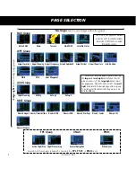
Page 10: ...ort Approach Airport Arrival Airport Departure Intersection NDB VOR User Waypoint NAV Group Default NAV Map NAVCOM Satellite Status Terrain AUX Group Flight Planning Utility Setup 1 Setup 2 Selection...

Page 11: ...arge right knob to highlight the Change Fields option and press ENT to select this option 3 Use the large right knob to highlight the data field you wish to change 4 Turn the small right knob to displ...

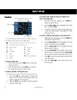
Page 12: ...ar adjacent to the map scale 2 Press the CLR key as needed to select the desired amount of map detail To Turn the Data Fields On Along the Right hand Side of the Map Page 1 With the Map Page displayed...

Page 13: ...30W highlight the desired frequency by scrolling through the list of frequencies as described in the previous procedure 2 To place a frequency in the standby field of the COM or VLOC window highlight...

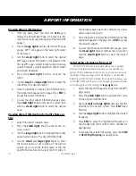
Page 14: ...enter the facility name or city location of the desired airport As you spell the facility name or city the Spell N Find feature will select the first entry in the database based upon the characters yo...

Page 15: ...e waypoint identifier field highlighted 2 Turn the large right knob to highlight the facility name second line or the city third line field 3 Use the small and large right knobs to enter the facility...

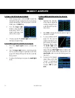
Page 16: ...hand side of the page will indicate which part of the list is currently being viewed 3 To remove the flashing cursor press the small right knob To View Additional Information for a Nearby Airport 1 Hi...

Page 17: ...ht Plan and press ENT To Stop Navigating a Flight Plan 1 Press FPL The Active Flight Plan Page will appear 2 Press MENU to display the Active Flight Plan Options 3 Turn the large right knob to highlig...

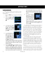
Page 18: ...receiver and external CDI or HSI for primary navi gation To confirm this reminder highlight Yes and press ENT Not all approaches in the database are approved for GPS use As you select an approach a G...

Page 19: ...ust first choose the airport then the approach procedure In the GNS 530W when a localizer based approach such as an ILS is loaded the desired frequency is automatically placed in standby on the VLOC w...

Page 20: ...r of the display Waypoint sequencing is automatically suspended indicated by SUSP directly above the OBS key at the holding waypoint Press the OBS key again to return to automatic waypoint sequencing...

Page 21: ...le in SW Ver 5 10 or later L VNAV Lateral Navigation and Vertical Navigation LNAV VNAV approach Fly to LNAV VNAV minimums LNAV V GPS approach using published LNAV minima Advisory vertical guidance is...

Page 22: ...20 190 00357 01 Rev H...

Page 23: ......

Page 24: ...Garmin Europe Ltd Liberty House Bulls Copse Road Hounsdown Business Park Southampton SO40 9RB U K Tel 44 0 870 850 1243 Fax 44 0 238 052 4004 Garmin Corporation No 68 Zhangshu 2nd Road Xizhi Dist New...

Reviews: