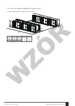
To prevent exposure to wind, install the unit with its
suction side facing the wall.
Never install the unit at a site where the suction side
may be exposed directly to wind.
To prevent exposure to wind, install a baffle plate on
the air discharge side of the unit.
In heavy snowfall areas, it is very important to select
an installation site where the snow will not affect the
unit. If lateral snowfall is possible, make sure that the
heat exchanger coil is not affected by the snow (if
necessary construct a lateral canopy).
6.1 Selecting a location in cold
climates
Refer to "Handling" in section “4 Before installation”
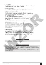
When operating the unit in cold climates, be sure
to follow the instructions described below.
NOTE
①
Construct a large canopy.
②
Construct a pedestal.
Install the unit high enough off the ground to prevent it
from being buried in snow.
6.2 Selecting a location in hot
climates
As the outdoor temperature is measured via the outdoor
unit air thermistor, make sure to install the outdoor unit in
the shade or a canopy should be constructed to avoild
direct sunlight, so that it is not influenced by the sun’s
heat, otherwise protection may be possible to the unit.
①
②
In case of strong wind and the wind direction can be
foreseen,refer to the figures below for installation of the
unit(any one is OK):
Turn the air outlet side toward the building's wall, fence
or screen.
Make sure there is enough room to do the installation.
Set the outlet side at a right angle to the direction of the
wind.
B(mm)
≥1000
≥1500
Unit
4~6kW
8~16kW
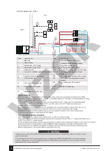
Prepare a water drainage channel around the
foundation, to drain waste water from around the unit.
If water does not easily drain from the unit, mount the
unit on a foundation of concrete blocks, etc. (the
height of the foundation should be about 100 mm
(3.93 in).
If you install the unit on a frame, please install a
waterproof plate (about 100 mm) on the underside of
the unit to prevent water from coming in from the low
side.
When installing the unit in a place frequently exposed
to snow, pay special attention to elevate the
foundation as high as possible.
If you install the unit on a building
frame, please install a waterproof
tray (field supply) (about 100mm, on
the underside of the unit) in order to
avoid drain water dripping. (See the
picture in the right).
A
B
A(mm)
≥300
≥300
Unit
4~6kW
8~16kW
Installation and operation manual - air-water heat pump Prima
© All rights reserved - Galmet Sp. z o.o. Sp. K.
98
WZÓR
Summary of Contents for Prima
Page 175: ...i 1 Galmet Sp z o o Sp K Prima 175 W Z R...
Page 176: ...3 1 3 1 Prima Galmet Sp z o o Sp K 176 W Z R...
Page 177: ...12 8 3 RCD 30 Galmet Sp z o o Sp K Prima 177 W Z R...
Page 181: ...5 6 EN378 5 CO2 50 CO2 12 24 50 CO2 500 CO2 12 500 CO2 Galmet Sp z o o Sp K Prima 181 W Z R...
Page 195: ...8 10 PCB B PCB B 4 6 PCB A PCB A 9 3 Galmet Sp z o o Sp K Prima 195 W Z R...
Page 206: ...9 4 3 3 3 3 2 60 9 4 4 Prima Galmet Sp z o o Sp K 206 W Z R...
Page 207: ...0 3 98 83 98 83 2 2 0 9 5 2 Galmet Sp z o o Sp K Prima 207 W Z R...
Page 208: ...30 9 7 2 30 0 1 9 7 1 9 6 9 7 B1 13 0 039 30 C 80 20 Prima Galmet Sp z o o Sp K 208 W Z R...
Page 215: ...9 1 9 2 9 1 9 2 9 3 Galmet Sp z o o Sp K Prima 215 W Z R...
Page 224: ...MENU BACK ON OFF UNLOCK C PCB E8 E0 E2 13 4 10 5 1 99 Prima Galmet Sp z o o Sp K 224 W Z R...
Page 235: ...11 11 1 50 11 2 10 5 11 12 10 1 24 9 4 4 pH pH 8 0 pH 7 0 Galmet Sp z o o Sp K Prima 235 W Z R...
Page 247: ...MCE P6 15 15 1 2 3 U V W 4 L1 L2 L3 5 Galmet Sp z o o Sp K Prima 247 W Z R...
Page 249: ...15 1 2 3 4 5 CO2 6 7 8 9 Galmet Sp z o o Sp K Prima 249 W Z R...
Page 250: ...11 12 13 14 25 OFN 15 b 10 Prima Galmet Sp z o o Sp K 250 W Z R...
Page 251: ...17 b c d e g h 80 i j k 18 19 20 16 Galmet Sp z o o Sp K Prima 251 W Z R...
Page 252: ...20 21 Y 4 A Prima Galmet Sp z o o Sp K 252 W Z R...
Page 253: ...XT3 XT3 8 10 4 6 K XT3 Galmet Sp z o o Sp K Prima 253 W Z R...
Page 254: ...XT3 XT3 12 14 16 1 K 40 200 230 12 14 16 3 Prima Galmet Sp z o o Sp K 254 W Z R...


