


the target during the move. In a tracking application, this could occur at any time during the move or at regularly
scheduled intervals. For example if a robot was designed to follow a moving object at a specified distance and the
path of the object wasn’t known the robot would be required to constantly monitor the motion of the object that it
was following. To remain within a specified distance it would also need to constantly update the position target it is
moving towards. Galil motion controllers support this type of motion with the position tracking mode. This mode
will allow scheduled or random updates to the current position target on the fly. Based on the new target the
controller will either continue in the direction it is heading, change the direction it is moving, or decelerate to a stop.
The position tracking mode shouldn’t be confused with the contour mode. The contour mode allows the user to
generate custom profiles by updating the reference position at a specific time rate. In this mode, the position can be
updated randomly or at a fixed time rate, but the velocity profile will always be trapezoidal with the parameters
specified by AC, DC, and SP. Updating the position target at a specific rate will not allow the user to create a
custom profile.
The following example will demonstrate the possible different motions that may be commanded by the controller in
the position tracking mode. In this example, there is a host program that will generate the absolute position targets.
The absolute target is determined based on the current information the host program has gathered on the object that
it is tracking. The position tracking mode does allow for all of the axes on the controller to be in this mode, but for
the sake of discussion, it is assumed that the robot is tracking only in the X dimension.
The controller must be placed in the position tracking mode to allow on the fly absolute position changes. This is
performed with the PT command. To place the X axis in this mode, the host would issue PT1 to the controller if
both X and Y axes were desired the command would be PT 1,1. The next step is to begin issuing PA command to
the controller. The BG command isn’t required in this mode, the SP, AC, and DC commands determine the shape of
the trapezoidal velocity profile that the controller will use.
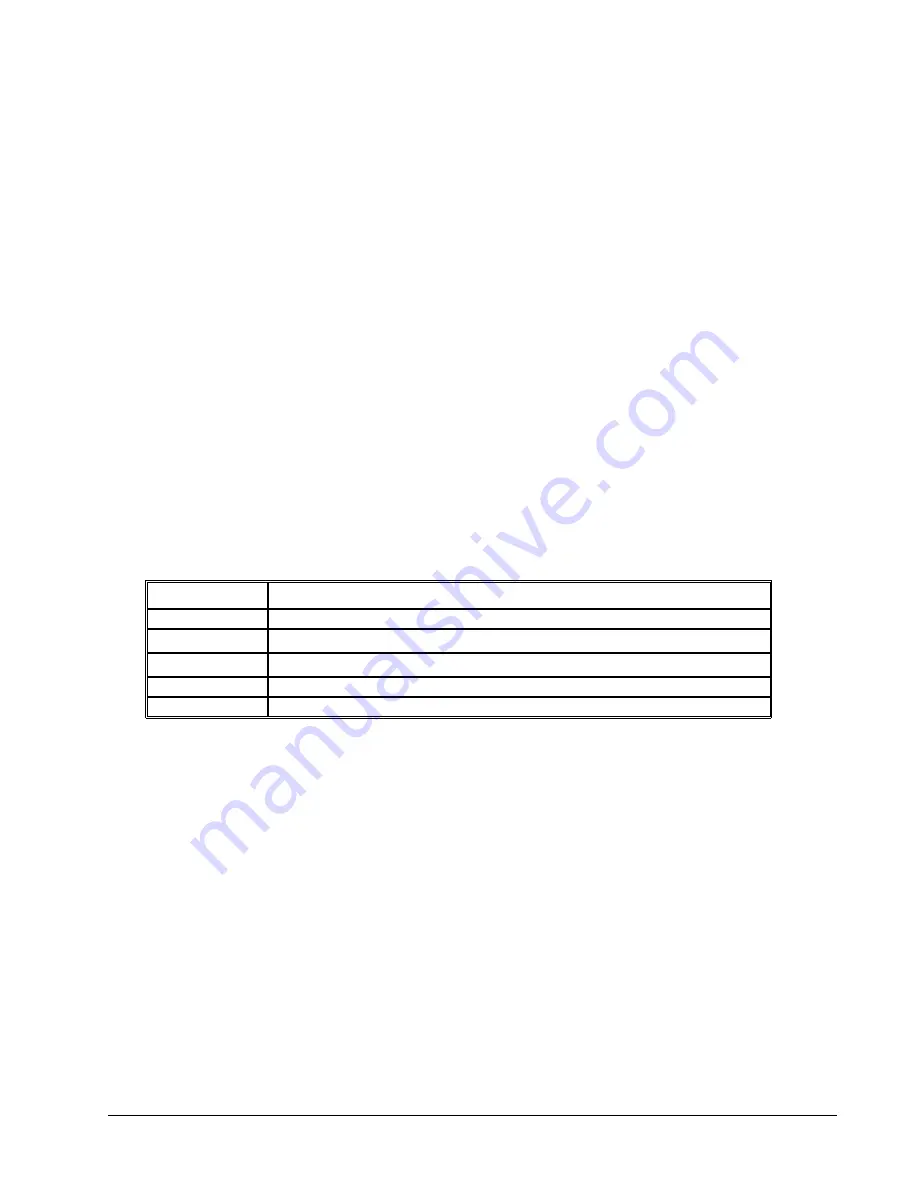
Example Motion 1: The host program determines that the first target for the controller to move to is located at 5000
encoder counts. The acceleration and deceleration should be set to 150,000 cts/sec2 and the velocity is set to 50,000
cts/sec. The command sequence to perform this is listed below.
Command
Description
PT1
Place the X axis in Position tracking mode
AC150000
Set the X axis acceleration to 150000 cts/sec
2
DC150000
Set the X axis deceleration to 150000 cts/sec
2
SP50000
Set the X axis speed to 50000 cts/sec
PA5000
Command the X axis to absolute position 5000 encoder counts
DMC-40x0 User Manual
Chapter 6 Programming Motion
•
82
Summary of Contents for DMC-4040
Page 54: ...Chapter 3 Connecting Hardware 45 DMC 40x0 User Manual...
Page 55: ...DMC 40x0 User Manual Chapter 3 Connecting Hardware 46...
Page 56: ...Chapter 3 Connecting Hardware 47 DMC 40x0 User Manual...
Page 73: ...Figure 4 1 GalilTools DMC 40x0 User Manual Chapter 4 Software Tools and Communication 64...
Page 185: ...THIS PAGE LEFT BLANK INTENTIONALLY DMC 40x0 User Manual Chapter 7 Application Programming 176...
Page 205: ...THIS PAGE LEFT BLANK INTENTIONALLY DMC 40x0 User Manual Chapter 10 Theory of Operation 196...
Page 222: ...Step 2 Remove ICM s Appendices 213 DMC 40x0 User Manual...
Page 232: ...DMC 4080 Steps 4 and 5 Step 4 Replace ICM s Appendices 223 DMC 40x0 User Manual...


