SuperPro Series Installation Manual
1 2 3 4 5 6 7 8
T R T R T R T R
Blue
Orange
Brown
Green
T=Tip(White with color stripe)
R=Ring(Color)
EIA/TIA 568A
Fig. 19
: EIA/TIA 568A Wire Standard
Pin 1
Pin 8
Fig. 20:
Literal Pin Out in the RJ45 Connector
(Latch down – NOT the wire punch down configuration)
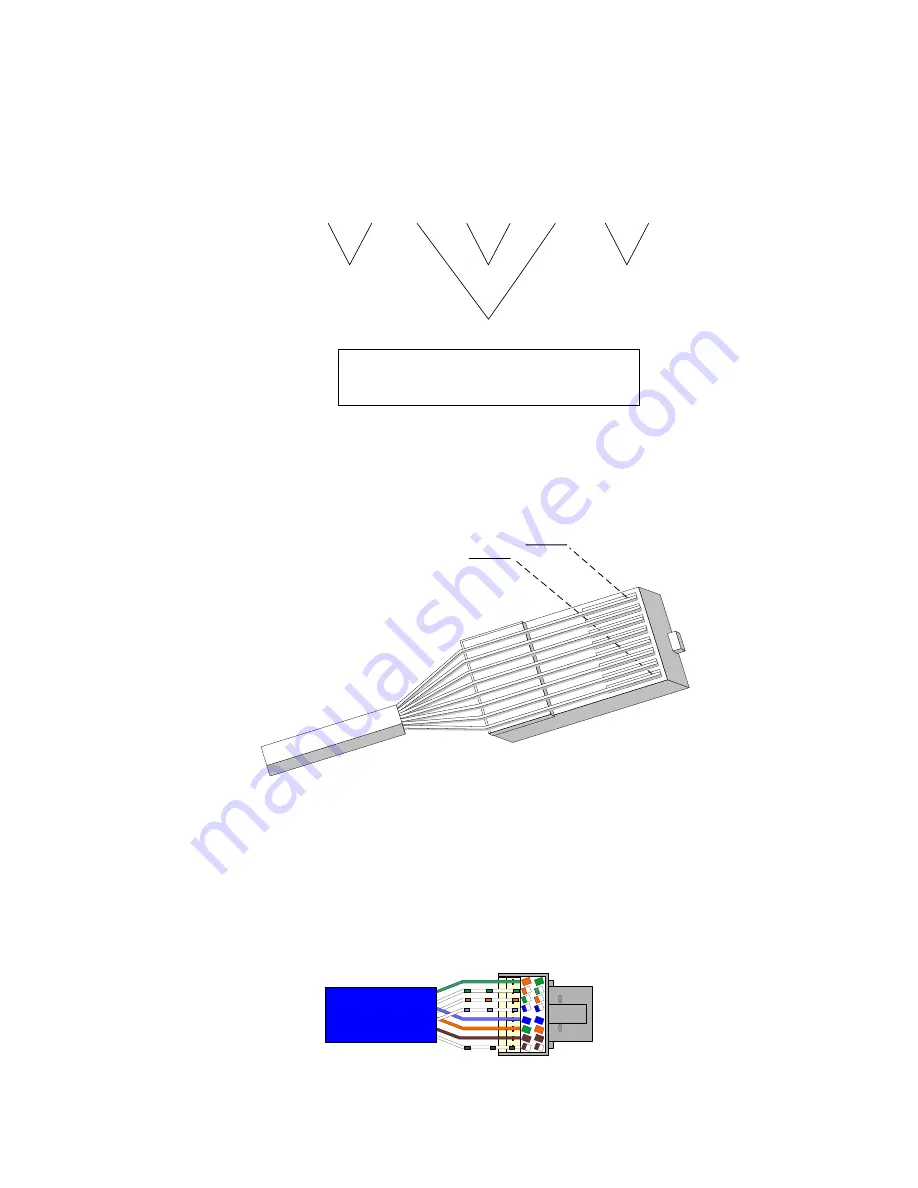
4. Select the yellow CAT5e cable, designate as data, and strip off a 1” section of its PVC jacket.
Untwist pairs ¾” from the end and straighten out conductors. Arrange conductors following
the 568A color-coded layout on the CAT5e connector (Figure 21).
5. Splay the wires out evenly and trim back, leaving 3/8” of untwisted conductors so they will
insert freely into the slots on the connector. Starting from right to left, insert each conductor
Fig. 21: Conductors Inserted in Connector
A
B
2
1
3
7
8
6
4
5
Page 16
FutureSmart


