4. INSTALLATION
45
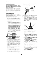
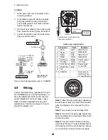
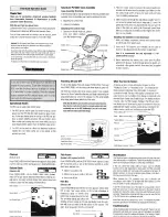
How to fix fuse holders
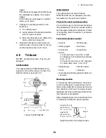
How to ground the display unit
• Use a 1.25 sq wire (local supply) for the
ground wire.
• Make the length of the ground wire as short
as possible and connect it to the boat’s
ground.
• For FRP vessel, attach a steel plate mea-
suring 20 cm by 30 cm on the outside of the
hull to provide a ground point. Connect the
ground wire there.
Note 1:
Use a ring-type lug (
) to make
the connection at the display unit. Do not use
a fork-type lug (
).
Note 2:
For the boat with positive polarity DC
power and the fish finder is grounded to the
hull, external equipment cannot be connected
directly to the fish finder if the signal line of the
equipment is connected to ground.
External equipment
The [12-24 VDC/NMEA] port is commonly
used for connection of external equipment
such as a GPS receiver and/or wind indicator.
This port is also used to connect the radio
transmitter for the Tankenmaru system. Refer
to the interconnection diagram to connect ca-
bles.
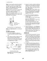
Speed/Temperature sensor
Connect the optional speed/temperature sen-
sor to the XDR port with the optional conver-
sion cable (Type 02S4147) as shown in the
opposite column.
Connection of conversion cable 02S4147
4.10
IEC 61162-1 Data
Sentences
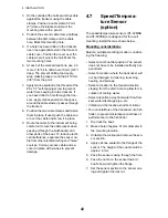
The table below shows the data sentences
which can be input to and output from your
fish finder. The transmission speed for both
input and output is 4,800 bps. Data is output
at two-second intervals.
Input/output data sentences
CAUTION
Be sure to ground the display unit.
An improper ground or no ground can affect perfor-
mance and cause interference to other equipment.
Fuse holder
Power supply lines
(red and black)
Cable tie
Sentence
Meaning
BWC
Bearing and distance to
waypoint
GGA
Global positioning system
(GPS) fix data
GLL
Geographic position - latitude/
longitude
GNS
GNSS fix data
HDG
Heading, deviation and varia-
tion
HDT
Heading, true
MDA
Atmospheric pressure
MTW
Water temperature.
MWV
Wind speed and angle
RMA
Recommended minimum
specific LORAN-C data
RMB
Recommended minimum
navigation information
RMC
Recommended minimum
specific GPS/TRANSIT data
Connect to XDR port
at rear of display unit
MJ-A10SPF
MJ-A6SRMD
MJ-A10SRMD
From
sensor
From
transducer
Tape connectors with
vulcanizing tape and
then vinyl tape to
waterproof them.
Bind tape ends with
cable ties to prevent
tape from unraveling.
Summary of Contents for FCV-627
Page 1: ...FISH FINDER FCV 627 OPERATOR S MANUAL www furuno com B R I L L GAIN ...
Page 62: ...D 1 ...
Page 63: ...D 2 ...


