2. WIRING
2-5
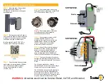
Waveguide connection at antenna unit
The signal cable entrance (cable gland) is located directly below the waveguide outlet. If the
waveguide is installed downward from the waveguide outlet position using an E-bend
waveguide, you may not be able to insert the signal cable into the cable gland. To avoid this
inconvenience, shift the waveguide run left or right using an H-bend waveguide as shown
below.
The E-band and H-band waveguides are contained in the waveguide materials set 22X-CW
or 52X-CW.
E-bend type RWA-1030 B-107, Code No. 310-100-140
H-bend type RWA-1050 C-109, Code No. 310-100-180
When the de-icer is installed
•
Before beginning any work on the antenna unit, turn off the breaker for the de-icer line at
the main switchboard to remove the power (100 VAC, 1
Ф
) to the de-icer. (Turning off the
power to the display unit has no effect.)
•
The neck of the antenna unit becomes VERY HOT when the de-icer is working. (The
de-icer turns on when ambient temperature is below 0˚C.)
Summary of Contents for FAR-2827W
Page 21: ...1 MOUNTING 1 11 Mounting of antenna unit ...
Page 34: ...1 MOUNTING 1 24 This page is intentionally left blank ...
Page 86: ...3 SETTING AND ADJUSTMENT 3 22 This page is intentionally left blank ...
Page 106: ...4 INSTALLING OPTIONAL EQUIPMENT 4 20 This page is intentionally left blank ...
Page 132: ......
Page 133: ......
Page 134: ...Jan 24 07 R Esumi ...
Page 135: ......
Page 136: ...May17 07 R Esumi ...
Page 137: ......
Page 138: ......
Page 139: ...Jan 18 08 R Esumi ...
Page 140: ...Apr 23 07 R Esumi ...
Page 141: ...Apr 23 07 R Esumi ...
Page 142: ...Apr 23 07 R Esumi ...
Page 143: ...Apr 23 07 R Esumi ...
Page 144: ...Apr 23 07 R Esumi ...
Page 145: ......
Page 146: ......
Page 147: ......
Page 148: ......
Page 149: ......
Page 150: ......
Page 151: ......
Page 152: ......
Page 153: ......
Page 154: ......


