background image

5-18

SPARC Enterprise T2000 Server Service Manual • April 2007
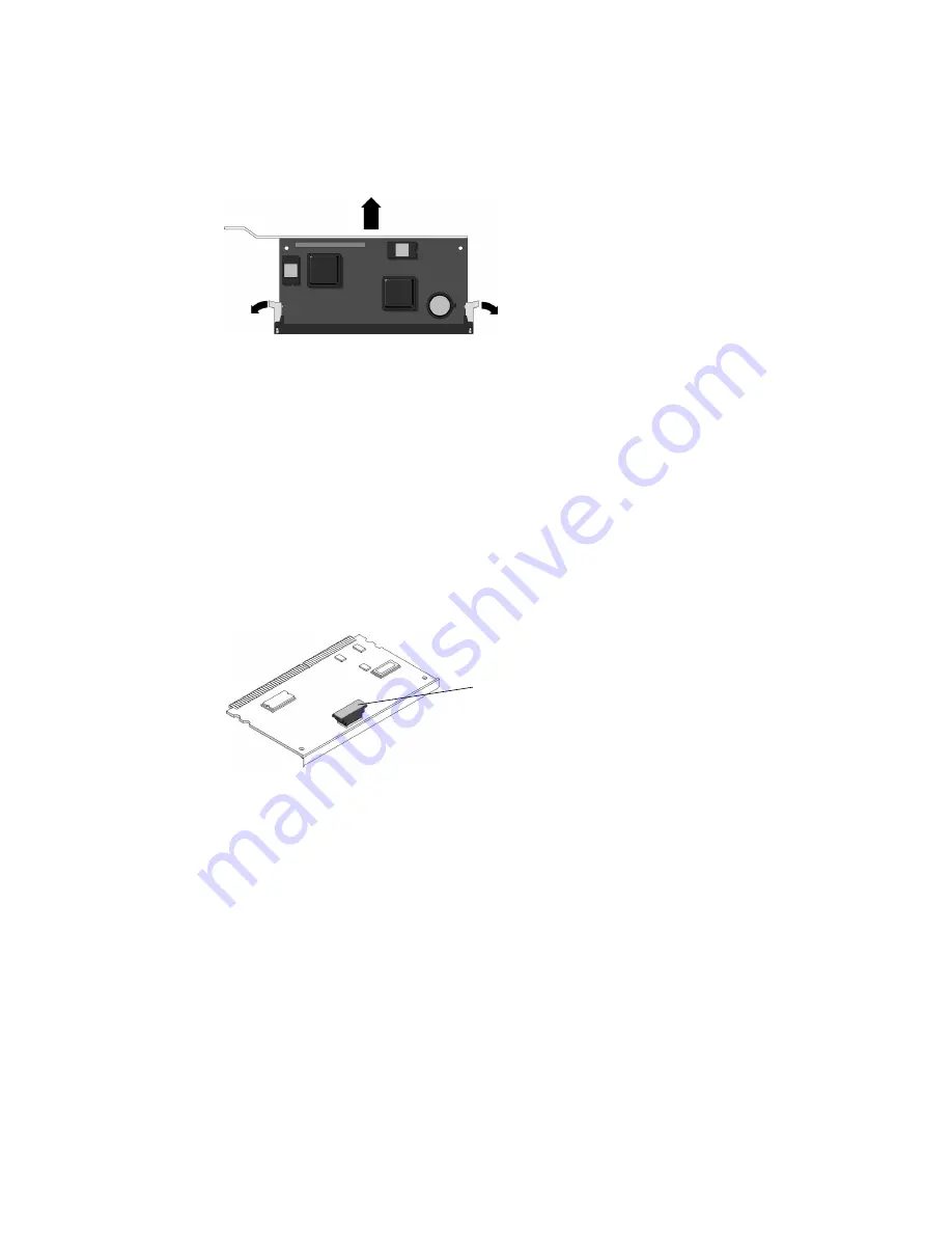
FIGURE 5-9

Ejecting and Removing the System Controller Card

4. Grasp the top corners of the card and pull it out of the socket.

5. Place the system controller card on an antistatic mat.

6. Remove the system configuration PROM (

FIGURE 5-10

from the system controller

and place it on an antistatic mat.

The system controller contains the persistent storage for the host ID and Ethernet
MAC addresses of the system, as well as the ALOM CMT configuration including
the IP addresses and ALOM CMT user accounts, if configured. This information will
be lost unless the system configuration PROM is removed and installed in the
replacement system controller. The PROM does not hold the fault data, and this data
will no longer be accessible when the system controller is replaced.

FIGURE 5-10

Locating the System Configuration PROM

5.2.6

Replacing the System Controller Card

1. Unpackage the replacement system controller card and place it on an antistatic

mat.

2. Install the system configuration PROM that you removed from the faulty system

controller card.

The PROM is keyed to ensure proper orientation.

3. Locate the system controller slot on the motherboard assembly.

System configuration
PROM

Summary of Contents for SPARC Enterprise T2000

Page 1: ......

Page 2: ......

Page 3: ...SPARC Enterprise T2000 Server Service Manual Manual Code C120 E377 01EN Part No 875 4036 10 April 2007 ...

Page 4: ... and the Fujitsu logo are registered trademarks of Fujitsu Limited All SPARC trademarks are used under license and are registered trademarks of SPARC International Inc in the U S and other countries Products bearing SPARC trademarks are based upon architecture developed by Sun Microsystems Inc SPARC64 is a trademark of SPARC International Inc used under license by Fujitsu Microelectronics Inc and ...

Page 5: ...Toutes les marques SPARC sont utilisées sous licence et sont des marques de fabrique ou des marques déposées de SPARC International Inc aux Etats Unis et dans d autres pays Les produits portant les marques SPARC sont basés sur une architecture développée par Sun Microsystems Inc SPARC64 est une marques déposée de SPARC International Inc utilisée sous le permis par Fujitsu Microelectronics Inc et F...

Page 6: ......

Page 7: ...2 1 Server Features 2 2 2 1 1 Chip Multitheaded Multicore Processor and Memory Technology 2 2 2 1 2 Performance Enhancements 2 3 2 1 3 Remote Manageability With ALOM CMT 2 5 2 1 4 System Reliability Availability and Serviceability 2 6 2 1 4 1 Hot Pluggable and Hot Swappable Components 2 6 2 1 4 2 Power Supply Redundancy 2 7 2 1 4 3 Fan Redundancy 2 7 2 1 4 4 Environmental Monitoring 2 7 2 1 4 5 Er...

Page 8: ... 1 Front and Rear Panel LEDs 3 8 3 2 2 Hard Drive LEDs 3 11 3 2 3 Power Supply LEDs 3 12 3 2 4 Fan LEDs 3 13 3 2 5 Blower Unit LED 3 13 3 2 6 Ethernet Port LEDs 3 14 3 3 Using ALOM CMT for Diagnosis and Repair Verification 3 16 3 3 1 Running ALOM CMT Service Related Commands 3 18 3 3 1 1 Connecting to ALOM CMT 3 18 3 3 1 2 Switching Between the System Console and ALOM CMT 3 18 3 3 1 3 Service Rela...

Page 9: ...Clearing PSH Detected Faults 3 44 3 6 Collecting Information From Solaris OS Files and Commands 3 45 3 6 1 Checking the Message Buffer 3 45 3 6 2 Viewing System Message Log Files 3 45 3 7 Managing Components With Automatic System Recovery Commands 3 46 3 7 1 Displaying System Components 3 47 3 7 2 Disabling Components 3 48 3 7 3 Enabling Disabled Components 3 48 3 8 Exercising the System With SunV...

Page 10: ...ement 5 1 5 1 1 Required Tools 5 2 5 1 2 Shutting the System Down 5 2 5 1 3 Extending the Server to the Maintenance Position 5 3 5 1 4 Removing the Server From a Rack 5 4 5 1 5 Disconnecting Power From the Server 5 6 5 1 6 Performing Electrostatic Discharge Prevention Measures 5 6 5 1 7 Removing the Top Cover 5 6 5 1 8 Removing the Front Bezel and Top Front Cover 5 7 5 2 Removing and Replacing FRU...

Page 11: ... 20 Replacing the SAS Disk Backplane 5 38 5 2 21 Removing the Battery on the System Controller 5 40 5 2 22 Replacing the Battery on the System Controller 5 40 5 3 Common Procedures for Finishing Up 5 41 5 3 1 Replacing the Top Front Cover and Front Bezel 5 41 5 3 2 Replacing the Top Cover 5 42 5 3 3 Reinstalling the Server Chassis in the Rack 5 42 5 3 4 Returning the Server to the Normal Rack Posi...

Page 12: ...prise T2000 Server Service Manual April 2007 6 2 3 PCI Express or PCI X Card Guidelines 6 7 6 2 4 Adding a PCI Express or PCI X Card 6 7 A Field Replaceable Units A 1 A 1 Illustrated FRU Locations A 2 Index Index 1 ...

Page 13: ...Supply LEDs 3 12 FIGURE 3 6 Location of Fan LEDs 3 13 FIGURE 3 7 Location of the Blower Unit LED 3 14 FIGURE 3 8 Ethernet Port LEDs 3 15 FIGURE 3 9 ALOM CMT Fault Management 3 16 FIGURE 3 10 Flowchart of ALOM CMT Variables for POST Configuration 3 29 FIGURE 3 11 SunVTS GUI 3 52 FIGURE 3 12 SunVTS Test Selection Panel 3 53 FIGURE 4 1 Fan Identification and Removal 4 3 FIGURE 4 2 Locating Power Supp...

Page 14: ... FIGURE 5 12 Cable Cutout 5 21 FIGURE 5 13 Location of the Screws in the Motherboard Assembly 5 22 FIGURE 5 14 Removing the Motherboard Assembly From the Server Chassis 5 23 FIGURE 5 15 Installing the Motherboard Assembly 5 25 FIGURE 5 16 Securing the Motherboard Assembly to the Chassis 5 26 FIGURE 5 17 Location of Power Supply Latch 5 28 FIGURE 5 18 Location of Bus Bar Screws on the Power Distrib...

Page 15: ...ng the Server to the Rack 5 43 FIGURE 5 31 Release Levers 5 44 FIGURE 5 32 Installing the CMA 5 45 FIGURE 6 1 Hard Drive Slots 6 3 FIGURE 6 2 Adding a USB Device 6 4 FIGURE 6 3 DIMM Layout 6 5 FIGURE 6 4 Location of PCI Express and PCI X Card Slots 6 7 FIGURE A 1 Field Replaceable Units 1 of 2 A 2 FIGURE A 2 Field Replaceable Units 2 of 2 A 3 ...

Page 16: ...xiv SPARC Enterprise T2000 Server Service Manual April 2007 ...

Page 17: ...Blower Unit LED 3 14 TABLE 3 7 Ethernet Port LEDs 3 15 TABLE 3 8 Service Related ALOM CMT Commands 3 19 TABLE 3 9 ALOM CMT Parameters Used For POST Configuration 3 27 TABLE 3 10 ALOM CMT Parameters and POST Modes 3 30 TABLE 3 11 ASR Commands 3 46 TABLE 3 12 Useful SunVTS Tests to Run on This Server 3 53 TABLE 5 1 DIMM Names and Socket Numbers 5 13 TABLE 6 1 DIMM Names and Socket Numbers 6 6 TABLE ...

Page 18: ...xvi SPARC Enterprise T2000 Server Service Manual April 2007 ...

Page 19: ...eplace internal components Understands the Solaris Operating System and the command line interface Has superuser privileges for the system being serviced Understands typical hardware troubleshooting tasks FOR SAFE OPERATION This manual contains important information regarding the use and handling of this product Read this manual thoroughly Pay special attention to the section Notes on Safety on pa...

Page 20: ... swappable and hot pluggable field replaceable units FRUs Chapter 5 Replacing Cold Swappable FRUs Describes how to remove and replace the FRUs that cannot be hot swapped Chapter 6 Adding New Components and Devices Explains how to add new components such as hard drives memory and PCI cards to the SPARC Enterprise T2000 server Appendix A Field Replaceable Units Provides an illustrated breakdown of p...

Page 21: ...ormation about where to find documentation to get your system installed and running quickly C120 E372 SPARC Enterprise T2000 Server Overview Guide Provides an overview of the features of this server C120 E373 SPARC Enterprise T2000 Server Installation Guide Detailed rackmounting cabling power on and configuring information C120 E376 SPARC Enterprise T2000 Server Administration Guide How to perform...

Page 22: ...ses the following fonts and symbols to express specific types of information The settings on your browser might differ from these settings Typeface Meaning Example AaBbCc123 The names of commands files and directories on screen computer output Edit your login file Use ls a to list all files You have mail AaBbCc123 What you type when contrasted with on screen computer output su Password AaBbCc123 B...

Page 23: ...This indicates a hazardous situation that could result in minor or moderate personal injury if the user does not perform the procedure correctly This signal also indicates that damage to the product or other property may occur if the user does not perform the procedure correctly Alert Messages in the Text An alert message in the text consists of a signal indicating an alert level followed by an al...

Page 24: ...uation could result in minor or moderate personal injury if the user does not perform the procedure correctly This signal also indicates that damage to the product or other property may occur if the user does not perform the procedure correctly Task Warning Maintenance Electric shock The system supplies standby power to the circuit boards even when the system is powered off Extremely hot The syste...

Page 25: ...nd inspections repairing and regular diagnosis and maintenance Caution The following tasks regarding this product and the optional products provided from Fujitsu should only be performed by a certified service engineer Users must not perform these tasks Incorrect operation of these tasks may cause malfunction Unpacking optional adapters and such packages delivered to the users Plugging or unpluggi...

Page 26: ...lowing labels provide information to the users of this product Fujitsu Welcomes Your Comments We would appreciate your comments and suggestions to improve this document You can submit your comments by using Reader s Comment Form For reinstall tighten to 7 in lbs LABEL P N 263 2644 01 Attach stabilizer M6 Screws and Cage Nuts Sample of SPARC Enterprise T2000 ...

Page 27: ...Preface xxv Reader s Comment Form ...

Page 28: ...D AND TAPE BUSINESS REPLY MAIL FIRST CLASS MAIL PERMIT NO 741 SUNNYVALE CA NO POSTAGE NECESSARY IF MAILED IN THE UNITED STATES POSTAGE WILL BE PAID BY ADDRESSEE FUJITSU COMPUTER SYSTEMS ATTENTION ENGINEERING OPS M S 249 1250 EAST ARQUES AVENUE P O BOX 3470 SUNNYVALE CA 94088 3470 ...

Page 29: ...rver For your protection observe the following safety precautions when setting up your equipment Follow all standard cautions warnings and instructions marked on the equipment and described in Important Safety Information for Hardware Systems C120 E391 Ensure that the voltage and frequency of your power source match the voltage and frequency inscribed on the equipment s electrical rating label Fol...

Page 30: ...rd drives contain electronic components that are extremely sensitive to static electricity Ordinary amounts of static electricity from clothing or the work environment can destroy components Do not touch the components along their connector edges 1 3 1 Using an Antistatic Wrist Strap Wear an antistatic wrist strap and use an antistatic mat when handling components such as drive assemblies boards o...

Page 31: ...APTER 2 Server Overview This chapter provides an overview of the features of the server The following topics are covered Section 2 1 Server Features on page 2 2 Section 2 2 Chassis Identification on page 2 9 ...

Page 32: ...erver The UltraSPARC T1 processor is based on chip multithreading CMT technology that is optimized for highly threaded transactional processing The UltraSPARC T1 processor improves throughput while using less power and dissipating less heat than conventional processor designs Depending on the model purchased the processor has four or eight UltraSPARC cores Each core equates to a 64 bit execution p...

Page 33: ...tuned for optimal performance FIGURE 2 2 Motherboard and UltraSPARC T1 Multicore Processor 2 1 2 Performance Enhancements The server introduces several new technologies with its sun4v architecture and multithreaded UltraSPARC T1 multicore processor Some of these enhancements are Large page optimization Reduction on TLB misses Optimized block copy UltraSPARC T1 multicore processor ...

Page 34: ...iating Internal hard drives 1 4 SAS 2 5 inch form factor drives hot pluggable Other internal peripherals 1 slimline DVD R CD RW device USB ports 4 USB 1 1 ports 2 in front and 2 in rear Cooling 3 hot swappable and redundant system fans and 1 blower unit PCI interfaces 3 PCI Express PCI E slots that support cards with the following specifications Low profile x1 x4 and x8 width 12v and 3 3v as defin...

Page 35: ...the server using the server s standby power Therefore ALOM CMT firmware and software continue to function when the server operating system goes offline or when the server is powered off ALOM CMT monitors the following server components CPU temperature conditions Hard drive status Enclosure thermal conditions Fan speed and status Power supply status Voltage levels Faults detected by POST power on s...

Page 36: ... reliability availability and serviceability the server offers the following features Hot pluggable hard drives Redundant hot swappable power supplies two Redundant hot swappable fan units three Environmental monitoring Error detection and correction for improved data integrity Easy access for most component replacements Extensive POST tests that automatically delete faulty components from the con...

Page 37: ...Hardware faults Temperature sensors located throughout the server monitor the ambient temperature of the server and internal components The software and hardware ensure that the temperatures within the enclosure do not exceed predetermined safe operating ranges If the temperature observed by a sensor falls below a low temperature threshold or rises above a high temperature threshold the monitoring...

Page 38: ...urately predict component failures and mitigate many serious problems before they occur This technology is incorporated into both the hardware and software of the server At the heart of the Predictive Self Healing capabilities is the Solaris Fault Manager a service that receives data relating to hardware and software errors and automatically and silently diagnoses the underlying problem Once a pro...

Page 39: ...GURE 2 3 Server Front Panel FIGURE 2 4 Server Rear Panel Hard drives DVD drive HDD 0 Indicators and buttons HDD 2 HDD 1 HDD 3 2 3 USB ports Power Power PCI E slot SC serial mgt SC net mgt Indicators PCI X slots TTYA serial GBE ports 2 0 1 3 0 1 USB ports port PCI E slots port port Slot 0 Slot 2 Slot 0 Slot 1 Slot 1 supply 1 supply 0 ...

Page 40: ...ssis serial number The chassis serial number is located on a sticker that is on the front of the server and another sticker on the side of the server You can also run the ALOM CMT showplatform command to obtain the chassis serial number Example sc showplatform SUNW SPARC Enterprise T2000 Chassis Serial Number 0529AP000882 Domain Status S0 OS Standby sc ...

Page 41: ...ing ALOM CMT for Diagnosis and Repair Verification on page 3 16 Section 3 4 Running POST on page 3 26 Section 3 5 Using the Solaris Predictive Self Healing Feature on page 3 40 Section 3 6 Collecting Information From Solaris OS Files and Commands on page 3 45 Section 3 7 Managing Components With Automatic System Recovery Commands on page 3 46 Section 3 8 Exercising the System With SunVTS on page 3...

Page 42: ...dations for repair The LEDs ALOM CMT Solaris OS PSH and many of the log files and console messages are integrated For example a fault detected by the Solaris software displays the fault logs it passes information to ALOM CMT where it is logged and depending on the fault might light one or more LEDs The flow chart in FIGURE 3 1 and TABLE 3 1 describes an approach for using the server diagnostics to...

Page 43: ...Chapter 3 Server Diagnostics 3 3 FIGURE 3 1 Diagnostic Flow Chart flowchart ...

Page 44: ... Healing PSH detected faults POST detected faults Faulty FRUs are identified in fault messages using the FRU name For a list of FRU names see Appendix A Section 3 3 2 Running the showfaults Command on page 3 21 3 Check the Solaris log files for fault information The Solaris message buffer and log files record system events and provide information about faults If system messages indicate a faulty d...

Page 45: ... environmental fault If the fault listed by the showfaults command displays a temperature or voltage fault then the fault is an environmental fault Environmental faults can be caused by faulty FRUs power supply fan or blower or by environmental conditions such as when computer room ambient temperature is too high or the server airflow is blocked When the environmental condition is corrected the fa...

Page 46: ...placed perform the procedure to clear PSH detected faults Section 3 5 Using the Solaris Predictive Self Healing Feature on page 3 40 Chapter 5 Section 3 5 2 Clearing PSH Detected Faults on page 3 44 8 Determine if the fault was detected by POST POST performs basic tests of the server components and reports faulty FRUs When POST detects a faulty FRU it logs the fault and if possible takes the FRU o...

Page 47: ...ory fault is detected POST displays the fault with the device name of the faulty DIMMS logs the fault and disables the faulty DIMMs by placing them in the ASR blacklist For a given memory fault POST disables half of the physical memory in the system When this offlining process occurs in normal operation you must replace the faulty DIMMs based on the fault message and enable the disabled DIMMs with...

Page 48: ...the instructions in that chapter to clear the faults and enable the replaced DIMMs 3 2 Using LEDs to Identify the State of Devices The server provides the following groups of LEDs Section 3 2 1 Front and Rear Panel LEDs on page 3 8 Section 3 2 2 Hard Drive LEDs on page 3 11 Section 3 2 3 Power Supply LEDs on page 3 12 Section 3 2 4 Fan LEDs on page 3 13 Section 3 2 5 Blower Unit LED on page 3 13 S...

Page 49: ... 3 9 FIGURE 3 2 Front Panel LEDs FIGURE 3 3 Rear Panel LEDs Locator LED button Power OK LED Top Fan LED Rear FRU Fault LED Over Temp LED Service Required LED Power On Off button Locator LED button Service Required LED Power OK LED ...

Page 50: ...he server is powered on and is running in its normal operating state Standby blink Indicates that the service processor is running while the server is running at a minimum level in standby mode and ready to be returned to its normal operating state Slow blink Indicates that a normal transitory activity is taking place Server diagnostics might be running or the system might be powering on Power on ...

Page 51: ...ed Steady on Indicates that a temperature failure event has been acknowledged and a service action is required View the ALOM CMT reports for further information on this event TABLE 3 3 Hard Drive LEDs LED Color Description OK to Remove Blue On The drive is ready for hot plug removal Off Normal operation Unused Amber Activity Green On Drive is receiving power Solidly lit if drive is idle Flashes wh...

Page 52: ...E 3 5 Power Supply LEDs TABLE 3 4 Power Supply LEDs LED Color Description Power OK Green On Normal operation DC output voltage is within normal limits Off Power is off Failure Amber On Power supply has detected a failure Off Normal operation AC OK Green On Normal operation Input power is within normal limits Off No input voltage or input voltage is below limits AC OK Fault Power OK ...

Page 53: ...FIGURE 3 6 FIGURE 3 6 Location of Fan LEDs 3 2 5 Blower Unit LED The blower unit LED is located on the back of the blower unit and visible from the rear of the server TABLE 3 6 TABLE 3 5 Fan LEDs LED Color Description Fan LEDs Amber On This fan is faulty Off Normal operation Note When a fan fault is detected the front panel Top Fan LED is lit Fault ...

Page 54: ...M CMT management Ethernet port and the four 10 100 1000 Mbps Ethernet ports each have two LEDs as shown in FIGURE 3 8 and described in TABLE 3 7 TABLE 3 6 Blower Unit LED LED Color Description Blower Unit LED Amber On The blower unit is faulty Off Normal operation Note When a blower fault is detected the Rear FRU Fault LED is lit Fault ...

Page 55: ... a Gigabit connection 1000 Mbps Green on The link is operating as a 100 Mbps connection Off The link is operating as a 10 Mbps connection The NET MGT port only operates in 100 Mbps or 10 Mbps so the speed indicator LED will be green or off never amber Right LED Green Link Activity indicator Steady on A link is established Blinking There is activity on this port Off No link is established ...

Page 56: ...irmware and software continue to function when the server OS goes offline or when the server is powered off Note Refer to the Advanced Lights Out Manager ALOM CMT Guide for comprehensive ALOM CMT information Faults detected by ALOM CMT POST and the Solaris Predictive Self healing PSH technology are forwarded to ALOM CMT for fault handling FIGURE 3 9 In the event of a system fault ALOM CMT ensures ...

Page 57: ...replacement Note ALOM CMT does not automatically detect hard drive replacement Many environmental faults can automatically recover A temperature that is exceeding a threshold might return to normal limits An unplugged a power supply can be plugged in and so on Recovery of environmental faults is automatically detected Recovery events are reported using one of two forms fru at location is OK sensor...

Page 58: ...l ways to connect to the system controller Connect an ASCII terminal directly to the serial management port Use the telnet command to connect to ALOM CMT through an Ethernet connection on the network management port Note Refer to the Advanced Lights Out Manager ALOM CMT Guide for instructions on configuring and connecting to ALOM CMT 3 3 1 2 Switching Between the System Console and ALOM CMT To swi...

Page 59: ... to have read and write capabilities consolehistory b lines e lines v g lines boot run Displays the contents of the system s console buffer The following options enable you to specify how the output is displayed g lines specifies the number of lines to display before pausing e lines displays n lines from the end of the buffer b lines displays n lines from beginning of buffer v displays entire buff...

Page 60: ...er supply front panel LED hard drive fan voltage and current sensor status See Section 3 3 3 Running the showenvironment Command on page 3 22 showfaults v Displays current system faults See Section 3 3 2 Running the showfaults Command on page 3 21 showfru g lines s d FRU Displays information about the FRUs in the server g lines specifies the number of lines to display before pausing the output to ...

Page 61: ...ve been passed to or detected by ALOM CMT To obtain the fault message ID SUNW MSG ID for PSH detected faults To verify that the replacement of a FRU has cleared the fault and not generated any additional faults At the sc prompt type the showfaults command The following showfaults command examples show the different kinds of output from the showfaults command Example of the showfaults command when ...

Page 62: ...tus front panel LED status voltage and current sensors The output uses a format similar to the Solaris OS command prtdiag 1m At the sc prompt type the showenvironment command The output differs according to your system s model and configuration Example sc showfaults v ID Time FRU Fault 1 OCT 13 12 47 27 MB CMP0 CH0 R0 D0 MB CMP0 CH0 R0 D0 deemed faulty and disabled sc showfaults v ID Time FRU Faul...

Page 63: ...ervice OK2RM HDD0 OK OFF OFF HDD1 OK OFF OFF HDD2 OK OFF OFF HDD3 OK OFF OFF Fans Status Fans Speeds Revolution Per Minute Sensor Status Speed Warn Low FT0 FM0 OK 3618 1920 FT0 FM1 OK 3437 1920 FT0 FM2 OK 3556 1920 FT2 OK 2578 1900 Voltage sensors in Volts Sensor Status Voltage LowSoft LowWarn HighWarn HighSoft MB V_ 1V5 OK 1 48 1 36 1 39 1 60 1 63 MB V_VMEML OK 1 78 1 69 1 72 1 87 1 90 MB V_VMEMR...

Page 64: ...9 IOBD V_ 1V OK 1 11 0 93 0 99 1 21 1 26 IOBD V_ 1V2 OK 1 17 1 02 1 08 1 32 1 38 IOBD V_ 5V OK 5 09 4 25 4 50 5 50 5 75 IOBD V_ 12V OK 12 11 13 80 13 20 10 80 10 20 IOBD V_ 12V OK 12 18 10 20 10 80 13 20 13 80 SC BAT V_BAT OK 3 03 2 69 System Load in amps Sensor Status Load Warn Shutdown MB I_VCORE OK 25 280 80 000 88 000 MB I_VMEML OK 4 680 60 000 66 000 MB I_VMEMR OK 4 680 60 000 66 000 Current ...

Page 65: ...on about the motherboard MB sc showfru MB SEEPROM SEGMENT SD ManR ManR UNIX_Timestamp32 WED OCT 12 18 24 28 2005 ManR Description ASSY SPARC Enterprise T2000 CPU Board ManR Manufacture Location Sriracha Chonburi Thailand ManR Sun Part No 5016843 ManR Sun Serial No NC00OD ManR Vendor Celestica ManR Initial HW Dash Level 06 ManR Initial HW Rev Level 02 ManR Shortname T2000_MB SpecPartNo 885 0483 04 ...

Page 66: ...ntended to test power on errors hardware upgrades or repairs Once the Solaris OS is running PSH provides run time diagnosis of faults Note Earlier versions of firmware have max as the default setting for the POST diag_level variable To set the default to min use the ALOM CMT command setsc diag_level min For validating hardware upgrades or repairs configure POST to run in maximum mode diag_level ma...

Page 67: ...redetermined settings stby The system cannot power on locked The system can power on and run POST but no flash updates can be made diag_mode off POST does not run normal Runs POST according to diag_level value service Runs POST with preset values for diag_level and diag_verbosity diag_level min If diag_mode normal runs minimum set of tests max If diag_mode normal runs all the minimum tests plus ex...

Page 68: ...splays functional tests with a banner and pinwheel normal POST output displays all test and informational messages max POST displays all test informational and some debugging messages TABLE 3 9 ALOM CMT Parameters Used For POST Configuration Continued Parameter Values Description ...

Page 69: ...Chapter 3 Server Diagnostics 3 29 FIGURE 3 10 Flowchart of ALOM CMT Variables for POST Configuration ...

Page 70: ... Diagnostic Preset Values diag_mode normal off service normal setkeyswitch The setkeyswitch parameter when set to diag overrides all the other ALOM CMT POST variables normal normal normal diag diag_level Earlier versions of firmware have max as the default setting for the POST diag_level variable To set the default to min use the ALOM CMT command setsc diag_level min min n a max max diag_trigger p...

Page 71: ...eventing faulty hardware from potentially harming software In normal operation diag_level min POST runs in mimimum mode by default to test devices required to power on the server Replace any devices POST detects as faulty in minimum mode Run POST in maximum mode diag_level max for all power on or error generated resets and to validate hardware upgrades or repairs With maximum testing enabled POST ...

Page 72: ... 1 Switch from the system console prompt to the sc prompt by issuing the escape sequence 2 Set the virtual keyswitch to diag so that POST will run in service mode 3 Reset the system so that POST runs There are several ways to initiate a reset The following example uses the powercycle command For other methods refer to the SPARC Enterprise T2000 Server Administration Guide ok sc sc setkeyswitch dia...

Page 73: ...test 0 0 CPU 0 0 0 DMMU Registers Access 0 0 IMMU Registers Access 0 0 Init mmu regs 0 0 D Cache RAM 0 0 Init MMU 0 0 DMMU TLB DATA RAM Access 0 0 DMMU TLB TAGS Access 0 0 DMMU CAM 0 0 IMMU TLB DATA RAM Access 0 0 IMMU TLB TAGS Access 0 0 IMMU CAM 0 0 Setup and Enable DMMU 0 0 Setup DMMU Miss Handler 0 0 Niagara Version 2 0 0 0 Serial Number 00000098 00000820 fffff231 17422755 0 0 Init JBUS Config...

Page 74: ...es at 00000000 00600000 Memory Channel 0 1 2 3 Rank 0 Stack 0 0 0 0 0 Test 4294967296 bytes at 00000001 00000000 Memory Channel 0 1 2 3 Rank 1 Stack 0 0 0 0 0 IO Bridge Tests 0 0 IO Bridge Quick Read 0 0 0 0 0 0 IO Bridge Quick Read Only of CSR and ID 0 0 0 0 fire 1 JBUSID 00000080 0f000000 0 0 IO Bridge unit 1 Config MB bridges 0 0 Config port A bus 2 dev 0 func 0 tag IOBD PCI SWITCH0 0 0 Config ...

Page 75: ...s use the following syntax INFO or WARNING message The following example shows a POST error message In this example POST is reporting a memory error at DIMM location MB CMP0 CH2 R0 D0 It was detected by POST running on core 7 strand 2 0 0 INFO 0 0 POST Passed all devices 0 0 Master set ACK for vbsc runpost command and spin 7 2 7 2 ERROR TEST Data Bitwalk 7 2 H W under test MB CMP0 CH2 R0 D0 S0 MB ...

Page 76: ...Correctable Errors Detected by POST In maximum mode POST detects and offlines memory devices with errors that could be correctable by PSH Use the examples in this section to verify if the detected memory devices are correctable Note For servers powered on in maximum mode without the intention of validating a hardware upgrade or repair examine all faults detected by POST to verify if the errors can...

Page 77: ...ds refer to the SPARC Enterprise T2000 Server Administration Guide 4 Replace the DIMM if POST continues to fault the device in minimum mode CODE EXAMPLE 3 1 POST Fault for a Single DIMM sc showfaults v ID Time FRU Fault 1 OCT 13 12 47 27 MB CMP0 CH0 R0 D0 MB CMP0 CH0 R0 D0 deemed faulty and disabled sc enablecomponent name of DIMM sc setkeyswitch normal sc setsc diag_mode normal sc setsc diag_leve...

Page 78: ...gle DIMM is detected replace the detected devices 2 If a detected device is a single DIMM and the same DIMM is also detected by PSH replace the DIMM CODE EXAMPLE 3 3 Note The detected DIMM in the previous example must also be replaced because it exceeds the PSH page retire threshold CODE EXAMPLE 3 2 POST Fault for Multiple DIMMs sc showfaults v ID Time FRU Fault 1 OCT 13 12 47 27 MB CMP0 CH0 R0 D0...

Page 79: ...ponents With Automatic System Recovery Commands on page 3 46 After the faulty FRU is replaced you must clear the fault by removing the component from the ASR blacklist This procedure describes how to do this 1 After replacing a faulty FRU at the ALOM CMT prompt use the showfaults command to identify POST detected faults POST detected faults are distinguished from other kinds of faults by the text ...

Page 80: ...ey negatively affect operations The Solaris OS uses the fault manager daemon fmd 1M which starts at boot time and runs in the background to monitor the system If a component generates an error the daemon handles the error by correlating the error with data from previous errors and other related information to diagnose the problem Once diagnosed the fault manager daemon assigns the problem a Univer...

Page 81: ...ying PSH Detected Faults When a PSH fault is detected a Solaris console message similar to the following is displayed SUNW MSG ID SUN4V 8000 DX TYPE Fault VER 1 SEVERITY Minor EVENT TIME Wed Sep 14 10 09 46 EDT 2005 PLATFORM SUNW SPARC Enterprise T2000 CSN HOSTNAME wgs48 37 SOURCE cpumem diagnosis REV 1 5 EVENT ID f92e9fbe 735e c218 cf87 9e1720a28004 DESC The number of errors associated with this ...

Page 82: ...H fmdump command the ALOM CMT showfaults command provides information about faults and displays fault UUIDs See Section 3 3 2 Running the showfaults Command on page 3 21 1 Check the event log using the fmdump command with v for verbose output In this example a fault is displayed indicating the following details Date and time of the fault Apr 24 06 54 08 2005 Universal Unique Identifier UUID that i...

Page 83: ...ns to repair the fault CPU errors exceeded acceptable levels Type Fault Severity Major Description The number of errors associated with this CPU has exceeded acceptable levels Automated Response The fault manager will attempt to remove the affected CPU from service Impact System performance may be affected Suggested Action for System Administrator Schedule a repair procedure to replace the affecte...

Page 84: ...ost detected fault Example If no fault is reported you do not need to do anything else Do not perform the subsequent steps If a fault is reported perform Step 2 through Step 4 3 Run the clearfault command with the UUID provided in the showfaults output 4 Clear the fault from all persistent fault records In some cases even though the fault is cleared some persistent fault information remains and re...

Page 85: ...es file 3 6 1 Checking the Message Buffer 1 Log in as superuser 2 Issue the dmesg command The dmesg command displays the most recent messages generated by the system 3 6 2 Viewing System Message Log Files The error logging daemon syslogd automatically records various system warnings errors and faults in message files These messages can alert you to system problems such as a device that is about to...

Page 86: ...ly disables a faulty component After the cause of the fault is repaired FRU replacement loose connector reseated and so on you must remove the component from the ASR blacklist The ASR commands TABLE 3 11 enable you to view and manually add or remove components from the ASR blacklist You run these commands from the ALOM CMT sc prompt more var adm messages more var adm messages TABLE 3 11 ASR Comman...

Page 87: ...sc prompt enter the showcomponent command Example with no disabled components sc showcomponent Keys MB CMP0 P0 MB CMP0 P1 MB CMP0 P2 MB CMP0 P3 MB CMP0 P8 MB CMP0 P9 MB CMP0 P10 MB CMP0 P11 MB CMP0 P12 MB CMP0 P13 MB CMP0 P14 MB CMP0 P15 MB CMP0 P16 MB CMP0 P17 MB CMP0 P18 MB CMP0 P19 MB CMP0 P20 MB CMP0 P21 MB CMP0 P22 MB CMP0 P23 MB CMP0 P28 MB CMP0 P29 MB CMP0 P30 MB CMP0 P31 MB CMP0 CH0 R0 D0 ...

Page 88: ...blecomponent command is complete reset the server so that the ASR command takes effect 3 7 3 Enabling Disabled Components The enablecomponent command enables a disabled component by removing it from the ASR blacklist 1 At the sc prompt enter the enablecomponent command sc showcomponent ASR state Disabled Devices MB CMP0 CH3 R1 D1 dimm15 deemed faulty sc disablecomponent MB CMP0 CH3 R1 D1 SC Alert ...

Page 89: ...ks necessary to use SunVTS software to exercise your server Section 3 8 1 Checking Whether SunVTS Software Is Installed on page 3 49 Section 3 8 2 Exercising the System Using SunVTS Software on page 3 50 3 8 1 Checking Whether SunVTS Software Is Installed This procedure assumes that the Solaris OS is running on the server and that you have access to the Solaris command line 1 Check for the presenc...

Page 90: ...res both character based and graphics based interfaces This procedure assumes that you are using the graphical user interface GUI on a system running the Common Desktop Environment CDE For more information about the character based SunVTS TTY interface and specifically for instructions on accessing it by tip or telnet commands refer to the SunVTS User s Guide SunVTS software can be run in several ...

Page 91: ...ype where test system is the name of the server you plan to test 3 Remotely log in to the server as superuser Use a command such as rlogin or telnet 4 Start SunVTS software If you have installed SunVTS software in a location other than the default opt directory alter the path in the following command accordingly where display system is the name of the machine through which you are remotely logged ...

Page 92: ...7 FIGURE 3 11 SunVTS GUI 5 Expand the test lists to see the individual tests The test selection area lists tests in categories such as Network as shown in FIGURE 3 12 To expand a category left click the icon expand category icon to the left of the category name ...

Page 93: ...SunVTS Tests to Run on This Server SunVTS Tests FRUs Exercised by Tests cmttest cputest fputest iutest l1dcachetest dtlbtest and l2sramtest indirectly mptest and systest DIMMS CPU motherboard disktest Disks cables disk backplane cddvdtest CD DVD device cable motherboard nettest netlbtest Network interface network cable CPU motherboard pmemtest vmemtest ramtest DIMMs motherboard serialtest I O seri...

Page 94: ...top button During testing SunVTS software logs all status and error messages To view these messages click the Log button or select Log Files from the Reports menu This action opens a log window from which you can choose to view the following logs Information Detailed versions of all the status and error messages that appear in the test messages area Test Error Detailed error messages from individu...

Page 95: ... field replaceable units FRUs in the server The following topics are covered Section 4 1 Devices That Are Hot Swappable and Hot Pluggable on page 4 2 Section 4 2 Hot Swapping a Fan on page 4 2 Section 4 3 Hot Swapping a Power Supply on page 4 4 Section 4 4 Hot Swapping the Rear Blower on page 4 7 Section 4 5 Hot Plugging a Hard Drive on page 4 9 ...

Page 96: ...ives can be hot swappable depending on how they are configured 4 2 Hot Swapping a Fan Three hot swappable fans are located under the fan door Two working fans are required to provide adequate cooling for the server If a fan fails replace it as soon as possible to ensure system availability The following LEDs are lit when a fan fault is detected Front and rear Service Required LEDs Top Fan LED on t...

Page 97: ...ion and Removal 2 Unpackage the replacement fan and place it near the server 3 Lift the latch on the top of the fan door FIGURE 4 1 and lift the fan door open The fan door is spring loaded and you must hold it in the open position 4 Identify the faulty fan A lighted LED on the top of a fan indicates that the fan is faulty 5 Pull up on the fan strap handle until the fan is removed from the fan bay ...

Page 98: ...ove and replace a power supply without shutting the server down provided that the other power supply is online and working The following LEDs are lit when a power supply fault is detected Front and rear Service Required LEDs Rear FRU Fault LED on the front of the server Amber Failure LED on the faulty power supply If a power supply fails and you do not have a replacement available leave the failed...

Page 99: ...hould not be removed because the other power supply is not providing power to the server Example In this command PSn is the power supply identifier for the power supply you plan to remove either PS0 or PS1 3 Gain access to the rear of the server where the faulty power supply is located 4 At the rear of the server release the cable management arm CMA tab FIGURE 4 3 and swing the CMA out of the way ...

Page 100: ...Replacing a Power Supply 1 Align the replacement power supply with the empty power supply bay 2 Slide the power supply into bay until it is fully seated 3 Reconnect the power cord to the power supply 4 Close the CMA inserting the end of the CMA into the rear left rail bracket 5 Verify that the amber LED on the replaced power supply the Service Required LED and Rear FRU Fault LEDs are not lit 6 At ...

Page 101: ...ted 2 Release the cable management arm tab FIGURE 4 3 and swing the cable management arm out of the way so you can access the power supply 3 Unscrew the two thumbscrews FIGURE 4 4 that secure the rear blower to the chassis FIGURE 4 4 Removing the Rear Blower 4 Grasp the thumbscrews and slowly slide the blower out of the chassis keeping the blower level as you remove it 4 4 2 Replacing the Rear Blo...

Page 102: ...2007 FIGURE 4 5 Replacing the Blower Unit 3 Tighten the two thumbscrews to secure the blower to the chassis 4 Verify that the Rear Blower and Service Required LEDs are not lit 5 Close the CMA inserting the end of the CMA into the rear left rail bracket FT2 ...

Page 103: ...e you can safely remove it The following situations inhibit the ability to perform hot plugging of a drive The hard drive provides the operating system and the operating system is not mirrored on another drive The hard drive cannot be logically isolated from the online operations of the server If your drive falls into these conditions you must shut the system down before you replace the hard drive...

Page 104: ...n to remove push the latch release button FIGURE 4 6 The latch opens Caution The latch is not an ejector Do not bend it too far to the left Doing so can damage the latch 4 Grasp the latch and pull the drive out of the drive slot 4 5 2 Replacing a Hard Drive 1 Align the replacement drive to the drive slot The hard drive is physically addressed according to the slot in which it is installed See FIGU...

Page 105: ... 3 Close the latch to lock the drive in place 4 Perform administrative tasks to reconfigure the hard drive The procedures that you perform at this point depend on how your data is configured You might need to partition the drive create file systems load data from backups or have data updated from a RAID configuration ...

Page 106: ...4 12 SPARC Enterprise T2000 Server Service Manual April 2007 ...

Page 107: ...t be in place for proper air flow The cover interlock switch intrusion switch immediately shuts the system down when the cover is removed 5 1 Common Procedures for Parts Replacement Before you can remove and replace parts that are inside the server you must perform the following procedures Section 5 1 2 Shutting the System Down on page 5 2 Section 5 1 3 Extending the Server to the Maintenance Posi...

Page 108: ... Log in as superuser or equivalent Depending on the nature of the problem you might want to view the system status the log files or run diagnostics before you shut down the system Refer to the SPARC Enterprise T2000 Server Administration Guide for log file information 2 Notify affected users Refer to your Solaris system administration documentation for additional information 3 Save any open files ...

Page 109: ... to the maintenance position Note Remove the server from the rack for all cold swappable FRU replacement procedures except the DIMMs PCI cards and the system controller 1 Optional Issue the following command from the ALOM CMT sc prompt to locate the system that requires maintenance Once you have located the server press the Locator LED button to turn it off 2 Check to see that no cables will be da...

Page 110: ...rver weighs approximately 40 lb 18 kg Two people are required to dismount and carry the chassis 1 Disconnect all the cables and power cords from the server 2 Extend the server to the maintenance position as described in Section 5 1 3 Extending the Server to the Maintenance Position on page 5 3 3 Press the metal lever FIGURE 5 2 that is located on the inner side of the rail to disconnect the CMA fr...

Page 111: ...ely 40 lb 18 kg The next step requires two people to dismount and carry the chassis 4 From the front of the server pull the release tabs forward and pull the server forward until it is free of the rack rails The release tabs are located on each rail about midway on the server 5 Set the server on a sturdy work surface ...

Page 112: ...emoval and installation Place ESD sensitive components such as the printed circuit boards on an antistatic mat The following items can be used as an antistatic mat Antistatic bag used to wrap a replacement part ESD mat part number 250 1088 Disposable ESD mat shipped with some replacement parts or optional system components 2 Attach an antistatic wrist strap When servicing or removing server compon...

Page 113: ...Front Cover The following field replaceable units FRUs require the removal of the top front cover and front bezel Motherboard SAS disk backplane LED board Front I O board Fan power board DVD 1 Remove the top cover as described in Section 5 1 7 Removing the Top Cover on page 5 6 2 Lift the fan cover latch FIGURE 5 3 and open the fan cover 3 Loosen the captive screw near the farthest right fan that ...

Page 114: ... procedures for replacing the following field replaceable parts FRUs inside the server chassis Section 5 2 1 Removing PCI Express and PCI X Cards on page 5 9 and Section 5 2 2 Replacing PCI Cards on page 5 11 Section 5 2 3 Removing DIMMs on page 5 12 and Section 5 2 4 Replacing DIMMs on page 5 14 Section 5 2 5 Removing the System Controller Card on page 5 17 and Section 5 2 6 Replacing the System ...

Page 115: ...the SAS Disk Backplane on page 5 38 Section 5 2 21 Removing the Battery on the System Controller on page 5 40 and Section 5 2 22 Replacing the Battery on the System Controller on page 5 40 To locate these FRUs refer to Appendix A 5 2 1 Removing PCI Express and PCI X Cards 1 Perform the procedures described in Section 5 1 Common Procedures for Parts Replacement on page 5 1 2 Locate the PCI card tha...

Page 116: ...April 2007 FIGURE 5 6 Location of PCI Express and PCI X Card Slots 4 Note and remove any cables that are attached to the card 5 Rotate the PCI hold down bracket 90 degrees so it no longer covers the PCI card FIGURE 5 7 PCI E slots 0 1 2 PCI X slots 0 1 ...

Page 117: ...ing PCI Cards 1 Unpackage the replacement PCI Express or PCI X card and place it on an antistatic mat 2 Locate the proper socket for the card you are replacing 3 Rotate the PCI hold down bracket 90 degrees so you can install the card 4 Insert the card into the socket 5 Rotate the PCI hold down bracket 90 degrees to lock the card in place 6 Perform the procedures described in Section 5 3 Common Pro...

Page 118: ...andle components that are sensitive to static discharges that can cause the component to fail To avoid this problem ensure that you follow antistatic practices as described in Section 5 1 6 Performing Electrostatic Discharge Prevention Measures on page 5 6 1 Perform the procedures described in Section 5 1 Common Procedures for Parts Replacement on page 5 1 2 Locate the DIMMs FIGURE 5 8 that you wa...

Page 119: ...ap DIMM names that are displayed in faults to socket numbers that identify the location of the DIMM on the motherboard TABLE 5 1 DIMM Names and Socket Numbers DIMM Name Used in Messages Socket No CH0 R1 D1 J0901 CH0 R0 D1 J0701 CH0 R1 D0 J0801 CH0 R0 D0 J0601 CH1 R1 D1 J1401 CH1 R0 D1 J1201 Front of board ...

Page 120: ...Line up the replacement DIMM with the connector Align the DIMM notch with the key in the connector This action ensures that the DIMM is oriented correctly 4 Push the DIMM into the connector until the ejector tabs lock the DIMM in place 5 Perform the procedures described in Section 5 3 Common Procedures for Finishing Up on page 5 41 CH1 R1 D0 J1301 CH1 R0 D0 J1101 CH2 R1 D1 J1901 CH2 R0 D1 J1701 CH...

Page 121: ... 8 For example If the fault resulted in the FRU being disabled such as the following Then run the enablecomponent command to enable the FRU 8 Perform the following steps to verify the repair a Set the virtual keyswitch to diag so that POST will run in Service mode b Issue the poweron command sc showfaults v ID Time FRU Fault 0 SEP 09 11 09 26 MB CMP0 CH0 R0 D0 Host detected fault MSGID SUN4V 8000 ...

Page 122: ...at the ok prompt type boot d Return the virtual keyswitch to normal mode e Issue the Solaris OS fmadm faulty command No memory or DIMM faults should be displayed If faults are reported refer to the diagnostics flowchart in FIGURE 3 1 for an approach to diagnose the fault 9 Gain access to the ALOM CMT sc prompt 10 Run the showfaults command sc console 0 0 POST Passed all devices 0 0 0 0 DEMON Diagn...

Page 123: ...tem Controller Card Caution The system controller card can be hot To avoid injury handle it carefully 1 Perform the procedures described in Section 5 1 Common Procedures for Parts Replacement on page 5 1 2 Locate the system controller card See Appendix A for an illustration of the servers FRUs that shows the system controller card 3 Push down on the ejector levers on each side of the system contro...

Page 124: ...he IP addresses and ALOM CMT user accounts if configured This information will be lost unless the system configuration PROM is removed and installed in the replacement system controller The PROM does not hold the fault data and this data will no longer be accessible when the system controller is replaced FIGURE 5 10 Locating the System Configuration PROM 5 2 6 Replacing the System Controller Card ...

Page 125: ... two distinct boards for the CPU and the I O board However they must be removed and replaced as a single motherboard assembly FIGURE 5 11 Caution Remove and replace the motherboard carefully The motherboard rests on metal standoffs If the motherboard is not handled carefully the components mounted on the underside of the motherboard can be damaged if they hit the standoffs To ensure that this dama...

Page 126: ...4 Remove all DIMMs from the motherboard assembly See Section 5 2 3 Removing DIMMs on page 5 12 Note the memory configuration so you can reinstall the memory in the replacement board 5 Remove the system controller card from the motherboard assembly See Section 5 2 5 Removing the System Controller Card on page 5 17 6 Disconnect cables from the motherboard assembly Disconnect the gray ribbon cable th...

Page 127: ...ssed through the cutout FIGURE 5 12 However the cable marked P8 is large and contains a number of small wires The cable will not easily pass through the cutout While pushing and pulling the cables through the cutout be careful not to damage the wires FIGURE 5 12 Cable Cutout 7 Remove the screws that secure the motherboard assembly to the chassis FIGURE 5 13 Caution Do not remove the screws that ho...

Page 128: ...ssembly 8 Lift the front of the motherboard to clear the front standoffs The front of the motherboard refers to the part of the motherboard nearest the front of the server 9 Slide the motherboard forward to clear the connectors from the cutouts in the rear of the chassis Flexible cable do not remove flex cable screws ...

Page 129: ...RE 5 14 Removing the Motherboard Assembly From the Server Chassis 11 Place the motherboard assembly on an antistatic mat 5 2 8 Replacing the Motherboard Assembly Caution Remove and replace the motherboard carefully The motherboard rests on metal standoffs If the motherboard is not handled carefully the components mounted on the underside of the motherboard can be damaged if they hit the standoffs ...

Page 130: ...bed in Section 5 1 6 Performing Electrostatic Discharge Prevention Measures on page 5 6 1 Unpackage the replacement motherboard assembly and place it on an antistatic mat 2 Tilt the motherboard assembly over the interior wall into the chassis FIGURE 5 15 and place it down on the rear standoffs Avoid touching the front standoffs with the motherboard 3 Slide the motherboard backward on the rear stan...

Page 131: ...ing the Motherboard Assembly 5 Adjust the position of the motherboard assembly so that it is mounted on the bus bar 6 Adjust the position of the motherboard assembly so that it lines up with the standoff screw holes 7 Loosely install two screws shown in FIGURE 5 16 ...

Page 132: ... the washer in this position even if the original motherboard did not have a washer 9 Tighten the two bus bar screws to secure the bus bar to the motherboard assembly 10 Reinstall the system controller card in the motherboard assembly See Section 5 2 6 Replacing the System Controller Card on page 5 18 11 Reinstall all DIMMs in the motherboard assembly in the slots from which they were removed See ...

Page 133: ...ctronic copy of the chassis serial number see Section 2 3 Obtaining the Chassis Serial Number on page 2 10 When you replace this board you must run certain service commands to update the replacement PDB with the chassis serial number The steps to perform these service commands are provided in Section 5 2 10 Replacing the Power Distribution Board on page 5 30 Caution The system supplies power to th...

Page 134: ... Power Supply Latch 3 Disconnect all cables from the PDB Disconnect the hard drive power connector from the PDB Release the latches on the DVD cable and disconnect it Disconnect the cable marked P7 Disconnect the blower power cable from the power distribution board Power supply latches ...

Page 135: ... FRUs 5 29 4 Remove the two screws that secure the power distribution board to the bus bar FIGURE 5 18 FIGURE 5 18 Location of Bus Bar Screws on the Power Distribution Board and the Motherboard Assembly Bus bar screws PDB mounting screw ...

Page 136: ...eplacing the Power Distribution Board Caution The system supplies power to the power distribution board even when the system is powered off To avoid personal injury or damage to the system you must disconnect all power cords before servicing the power distribution board 1 Loosely fit the power distribution board PDB onto the locator pins in the chassis and slide the board toward the rear of the ch...

Page 137: ...d on a sticker on the side of the server The serial number is unique to each server You need this number for subsequent steps in this procedure 7 Perform the procedures described in Section 5 3 Common Procedures for Finishing Up on page 5 41 and then return to this procedure to complete the remaining steps Note After replacing the power distribution board and powering on the system you must run th...

Page 138: ...ts SUNW SPARC Enterprise T2000 the setpartner c 1 command was executed correctly 5 2 11 Removing the LED Board 1 Perform the procedures described in Section 5 1 Common Procedures for Parts Replacement on page 5 1 2 Remove all three fans See Section 4 2 1 Removing a Fan on page 4 2 sc setsc sc_servicemode true Warning misuse of this mode may invalidate your warranty sc setcsn c chassis serial numbe...

Page 139: ...ve the LED board from the chassis and place it on an antistatic mat 5 2 12 Replacing the LED Board 1 Install the LED board in the chassis 2 Slide the board to the left to connect it to the front I O board 3 Secure the LED board to the chassis using two M3x6 flat head screws FIGURE 5 21 4 Replace all three fans See Section 4 2 2 Replacing a Fan on page 4 4 5 Perform the procedures described in Sect...

Page 140: ... 1 Removing a Fan on page 4 2 3 Remove the screw that secures the fan power board to the chassis FIGURE 5 22 4 Slide the fan power board to the right to disengage it from the front I O board 5 Remove the fan power board from the front fan bay and place the board on an antistatic mat FIGURE 5 22 Removing the Fan Power Board 5 2 14 Replacing the Fan Power Board 1 Unpackage the replacement fan power ...

Page 141: ...rform the procedures described in Section 5 1 Common Procedures for Parts Replacement on page 5 1 2 Remove all three fans See Section 4 2 1 Removing a Fan on page 4 2 3 Disengage the fan power board from the front I O board Step 3 and Step 4 in Section 5 2 13 Removing the Fan Power Board on page 5 34 4 Remove the fan guard to gain access to the M3x6 flat head screw that secures the front I O board...

Page 142: ... the front I O board on an antistatic mat 5 2 16 Replacing the Front I O Board 1 Unpackage the front I O board and place it on an antistatic mat 2 Tip the front I O board downwards and slightly forward and push it into place aligning the board with the screw hole in the exterior wall of the chassis When the board is fully seated both connectors on the USB ports are mounted flush against the mother...

Page 143: ...de the DVD drive into the front of the chassis 2 Replace the DVD interconnect board on the back of the DVD drive 3 Perform the procedures described in Section 5 3 Common Procedures for Finishing Up on page 5 41 5 2 19 Removing the SAS Disk Backplane 1 Perform the procedures described in Section 5 1 Common Procedures for Parts Replacement on page 5 1 2 Remove the DVD from the chassis See Section 5 ...

Page 144: ...m the chassis and place it on an antistatic mat 5 2 20 Replacing the SAS Disk Backplane 1 Unpackage the replacement SAS disk backplane and place it on an antistatic mat 2 Place the SAS disk backplane on the two ledges on the bottom of the drive cage assembly with the power connector facing down toward the bottom of the chassis The ledges hold the backplane in place temporarily SAS disk backplane P...

Page 145: ...er with each screw even if the original SAS disk backplane did not have any washers FIGURE 5 26 Replacing the SAS Disk Backplane 4 Connect the SAS power cable from the power cable connector 5 Connect the four SAS data cables to the replacement SAS disk backplane ensuring that you connect the cables in the same positions on the replacement SAS disk backplane 6 Reinstall all four hard drives in the ...

Page 146: ...ssis Section 5 2 5 Removing the System Controller Card on page 5 17 and place the system controller on an antistatic mat 3 Using a small flat head screwdriver carefully pry the battery FIGURE 5 27 from the system controller FIGURE 5 27 Removing the Battery From the System Controller 5 2 22 Replacing the Battery on the System Controller 1 Unpackage the replacement battery 2 Press the new battery in...

Page 147: ...y and time Use the setdate command before you power on the host system For details about this command refer to the Advanced Lights Out Management ALOM CMT Guide 5 3 Common Procedures for Finishing Up 5 3 1 Replacing the Top Front Cover and Front Bezel 1 Place the top front cover on the chassis 2 Slide the front top cover forward until it snaps into place being careful to avoid catching the cover o...

Page 148: ...r down so that it hangs over the rear of the server by about an inch 2 Slide the cover forward until it latches into place 5 3 3 Reinstalling the Server Chassis in the Rack If you removed the server chassis from the rack perform these steps Caution The server weighs approximately 40 lb 18 kg Two people are required to carry the chassis and install it in the rack 1 Ensure that the rack rails are ex...

Page 149: ... The server is now in the extended maintenace position 5 3 4 Returning the Server to the Normal Rack Position If you extended the server to the maintenance position use this procedure to return the server to the normal rack position 1 Release the slide rails from the fully extended position by pushing the release levers on the side of each rail FIGURE 5 31 ...

Page 150: ...server into the rack Ensure that the cables do not get in the way 3 Reconnect the CMA into the back of the rail assembly Note Refer to the SPARC Enterprise T2000 Server Installation Guide for detailed CMA installation instructions a Insert the inner latch smaller right side into the clip located at the end of the mounting bracket FIGURE 5 32 ...

Page 151: ... extension clicks into place 4 Reconnect the cables to the back of the server If the CMA is in the way disconnect the left CMA release and swing the CMA open 5 3 5 Applying Power to the Server Reconnect both power cords to the power supplies Note As soon as the power cords are connected standby power is applied and depending on the configuration of the firmware the system might boot ...

Page 152: ...5 46 SPARC Enterprise T2000 Server Service Manual April 2007 ...

Page 153: ...administration during installation Hot swappable devices such as USB devices can be connected to and disconnected from the system while the system is running Other components and devices require you to shut down the system prior to installation See Section 6 2 Adding Components Inside the Chassis on page 6 4 6 1 1 Adding a Hard Drive to the Server Hard drives are physically addressed according to ...

Page 154: ... chassis a On the blank panel push the latch release button b Grasp the latch and pull the blank panel out 2 Align the disk drive to the drive bay slot See FIGURE 6 1 For additional details see Section 4 5 1 Removing a Hard Drive on page 4 9 3 Slide the hard drive into the bay until the drive is fully seated 4 Close the hard drive lever to lock the drive in place 5 Use cfgadm al to list all disks ...

Page 155: ...ng You can connect up to 126 devices to each of the two USB controllers each controller provides two connectors for a total of 252 USB devices The USB ports on the server support USB 1 1 devices Note There are many USB devices on the market Read the product documentation for your USB device for additional installation requirements and instructions that are not covered here Plug a standard USB devi...

Page 156: ... the server Memory PCI X cards PCI Express cards 6 2 1 Memory Guidelines Use the following guidelines and FIGURE 6 3 and TABLE 6 1 to plan the memory configuration of your server There are 16 slots that hold DDR2 memory DIMMs The server accepts the following DIMM sizes 512 MB 1 GB 2 GB 4 GB The server supports two ranks of eight DIMMs each Front USB ports Rear USB ports ...

Page 157: ...New Components and Devices 6 5 At minimum rank 0 must be fully populated with eight DIMMS of the same capacity DIMMs can be added eight at a time of the same capacity to fill rank 1 FIGURE 6 3 DIMM Layout Front of board ...

Page 158: ...osition 4 Line up the DIMM with the connector 5 Push the DIMM into the connector until the ejector tabs lock the DIMM in place 6 Repeat Step 3 through Step 5 for each additional DIMM TABLE 6 1 DIMM Names and Socket Numbers DIMM Name Socket Number Rank 0 DIMMs CH0 R0 D1 J0701 CH0 R0 D0 J0601 CH1 R0 D1 J1201 CH1 R0 D0 J1101 CH2 R0 D1 J1701 CH2 R0 D0 J1601 CH3 R0 D1 J2201 CH3 R0 D0 J2101 Rank 1 DIMMs...

Page 159: ...lots for low profile cards supports lane widths of x1 x2 x4 and x8 2 PCI X slots for low profile cards Note There are a variety of PCI X and PCI Express cards on the market Read the product documentation for your device for additional installation requirements and instructions that are not covered here FIGURE 6 4 Location of PCI Express and PCI X Card Slots 6 2 4 Adding a PCI Express or PCI X Card...

Page 160: ...crew that holds the bracket to the chassis 3 Line up the PCI card with the PCI connector on the rear of the motherboard 4 Push the card into the connector so it is fully seated 5 Rotate the PCI hold down bracket to the closed position and secure the screw on the bracket 6 Install any cables that go to the PCI card 7 Perform the procedures described in Section 5 1 Common Procedures for Parts Replac...

Page 161: ...NDIX A Field Replaceable Units This appendix provides illustrated parts breakdown diagrams and a table that lists the server FRUs The following topic is covered Section A 1 Illustrated FRU Locations on page A 2 ...

Page 162: ... Server Service Manual April 2007 A 1 Illustrated FRU Locations FIGURE A 1 FIGURE A 2 and TABLE A 1 list the locations of the field replaceable units FRUS in the server FIGURE A 1 Field Replaceable Units 1 of 2 1 5 2 6 8 9 3 4 7 ...

Page 163: ...Appendix A Field Replaceable Units A 3 FIGURE A 2 Field Replaceable Units 2 of 2 13 11 12 10 14 16 15 ...

Page 164: ...gurations to accommodate the different processor models 4 6 and 8 core MB IOBD 2 System controller card OSP board Section 5 2 5 Removing the System Controller Card on page 5 17 This board implements the system controller subsystem The SC board contains a PowerPC Extended Core and a communications processor that controls the host power and monitors host system events power and environmental The boa...

Page 165: ...ply on page 4 4 The power supplies provide 3 3 Vdc standby power at 3 Amps and 12 Vdc at 25 Amps When facing the rear of the system PS0 is on the left and PS1 is on the right PS0 PS1 9 Rear blower Section 4 4 1 Removing the Rear Blower on page 4 7 Blower FT2 10 LED board Section 5 2 11 Removing the LED Board on page 5 32 Contains the push button circuitry and LEDs that are displayed on the front b...

Page 166: ...tion vertical SAS connectors that bring each of the four SAS links from the I O board This board contains the electronic chassis serial number SASBP 15 Hard drives Section 4 5 1 Removing a Hard Drive on page 4 9 SFF SAS 2 5 inch form factor hard drives HDD0 HDD1 HDD2 HDD3 16 DVD drive Section 5 2 17 Removing the DVD Drive on page 5 37 DVD CD ROM drive DVD The FRU name is used in system messages TA...

Page 167: ...6 3 48 asrkeys 3 47 Automatic System Recovery ASR 3 46 B battery system controller A 4 replacing 5 40 bezel removing 5 7 replacing 5 42 blacklist ASR 3 46 block copy optimized 2 3 blower 4 2 fault LED 3 13 removing 4 7 replacing 4 7 bootmode command 3 19 break command 3 19 bus bar screws 5 26 5 29 button Locator 5 3 Power On Off 3 10 5 3 top cover release 5 7 C cable kit A 5 cable management arm C...

Page 168: ...13 6 5 troubleshooting 3 8 disablecomponent command 3 46 3 48 disabled component 3 48 disabled DIMMs 5 15 disk drives see hard drives displaying FRU status 3 25 dmesg command 3 45 DVD drive A 6 removing 5 37 replacing 5 37 DVD drive FRU name A 6 DVD specification 2 4 E electrostatic discharge ESD prevention 1 2 5 6 enablecomponent command 3 40 3 46 3 48 5 15 environmental faults 3 4 3 5 3 17 3 21 ...

Page 169: ...ssignments 6 3 specifications 2 4 status displaying 3 22 hardware components sanity check 3 31 HDD hard drive FRU names A 6 help command 3 19 host ID 5 18 hot pluggable devices adding 6 1 hot plugging hard drives 4 9 hot swappable devices fans 4 2 FRUs 4 1 overview 2 6 power supplies 4 4 I I O board see also motherboard 5 19 identification of chassis 2 9 indicators 3 8 installing additional device...

Page 170: ...mes A 4 PCI capabilities 6 7 PCI hold down bracket 5 10 PCI E and PCI X cards adding 6 7 designations A 4 replacing 5 11 PCI E and PCI X interface specifications 2 4 PDB power distribution board FRU name A 5 performance enhancements 2 3 platform name 2 4 POST detected faults 3 4 3 21 POST see also power on self test POST 3 26 power cords disconnecting 5 6 reconnecting 5 45 power distribution board...

Page 171: ... distribution board 5 27 SAS disk backplane 5 37 server from the rack 5 4 system controller card 5 17 top cover 5 6 replacing battery on the system controller 5 40 DIMMs 5 14 DVD drive 5 37 fan power board 5 34 front I O board 5 36 LED board 5 33 motherboard assembly 5 23 PCI cards 5 11 power distribution board 5 30 SAS disk backplane 5 38 system controller card 5 18 top cover 5 42 top front cover...

Page 172: ...interfaces 3 50 3 51 3 53 3 54 support obtaining 3 5 switch intrusion 5 1 syslogd daemon 3 45 system configuration PROM 5 18 system console switching to 3 18 system controller 3 2 system controller card A 4 battery 5 40 removing 5 17 replacing 5 18 system temperatures displaying 3 22 T temperature sensors 2 7 TLB misses reduction of 2 3 tools required 5 2 top cover release button 5 7 removing 5 6 ...

Page 173: ......

Page 174: ......

Reviews: