background image

SH-E514TR1 10 Gigabit Ethernet SmartPro Switch User Manual


58


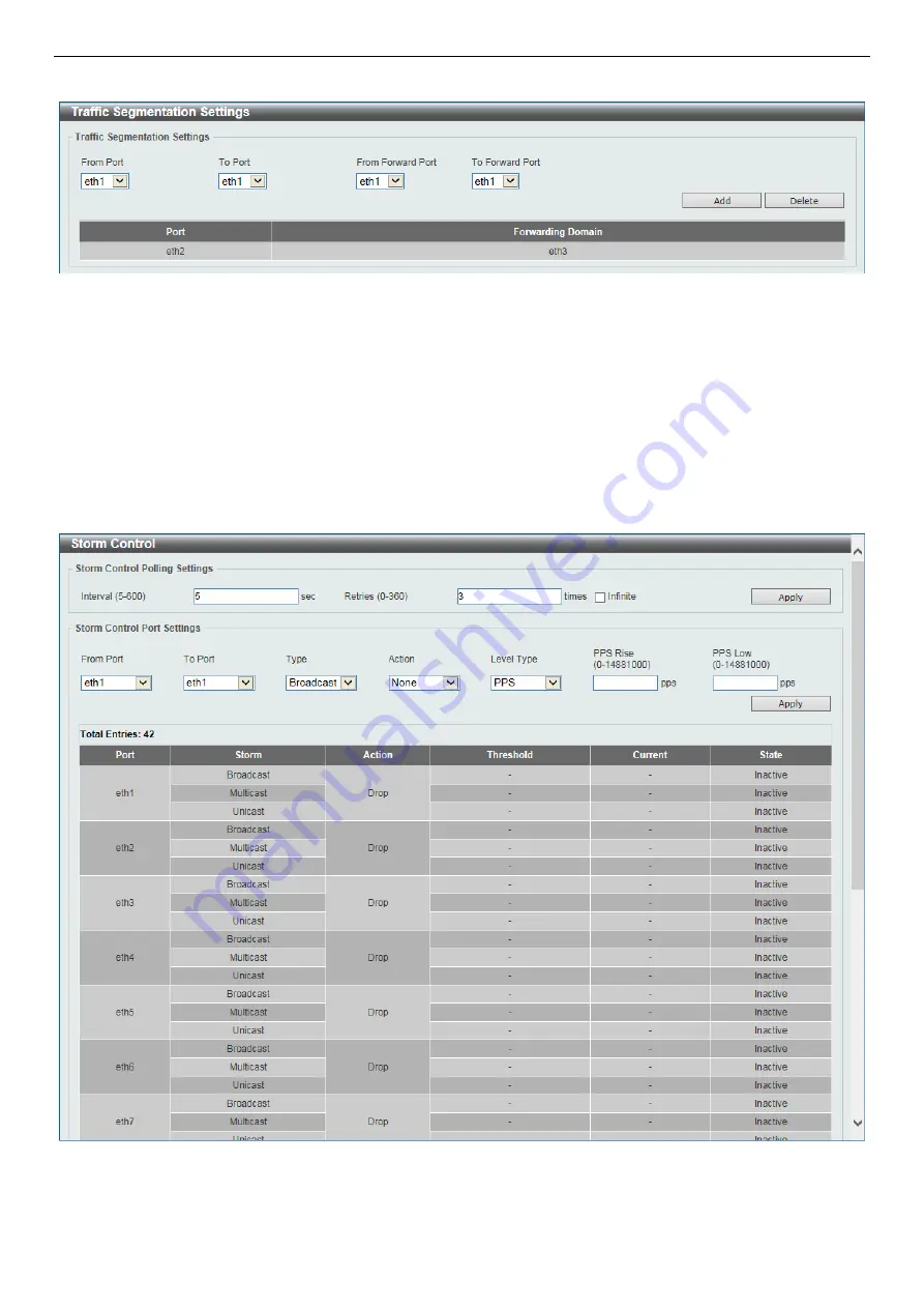
If the forwarding domain of an interface is empty, then there is no restriction on Layer 2 forwarding of packets received 
by the port. 


Figure 12-4 Traffic Segmentation Settings 


The fields that can be configured are described below: 

From Port / To Port: 

Select the receiving port range used for the configuration here. 

From Forward Port / To Forward Port:

 Select the forward port range used for the configuration here. 


Click 

Add

 to add a new entry based on the information entered. 

Click 

Delete

 to remove a new entry based on the information entered. 


Storm Control 

This window is used to view and configure the storm control settings. 


Figure 12-5 Storm Control 


The fields that can be configured are described below: 

Summary of Contents for SH-E514TR1 10

Page 1: ...Fujutsu SH E514TR1 10 Gigabit Ethernet SmartPro Switch User Manual ...

Page 2: ...las medidas adecuadas Attention Ceci est un produit de classe A Dans un environnement domestique ce produit pourrait causer des interférences radio auquel cas l utilisateur devrait prendre les mesures adéquates Attenzione Il presente prodotto appartiene alla classe A Se utilizzato in ambiente domestico il prodotto può causare interferenze radio nel cui caso è possibile che l utente debba assumere ...

Page 3: ...TP 9 Firmware Backup to HTTP 9 Firmware Backup to TFTP 10 Configuration Restore and Backup 10 Configuration Restore from HTTP 10 Configuration Restore from TFTP 11 Configuration Backup to HTTP 11 Configuration Backup to TFTP 11 Log Backup 12 Log Backup to HTTP 12 Log Backup to TFTP 12 Ping 13 Reset 13 Reboot System 14 6 Device Information 15 7 System 16 System Information Settings 16 Peripheral Se...

Page 4: ...32 MAC Address Table Settings 33 MAC Address Table 33 VLAN 34 802 1Q VLAN 34 VLAN Interface 35 STP 37 STP Global Settings 37 STP Port Settings 38 STP Global Information 40 STP Port Information 40 Link Aggregation 40 L2 Multicast Control 42 IGMP Snooping 42 IGMP Snooping Settings 42 IGMP Snooping Groups Settings 45 IGMP Snooping Mrouter Settings 45 IGMP Snooping Statistics Settings 46 Multicast Fil...

Page 5: ...lobal Settings 56 Port Security Port Settings 56 Port Security Address Entries 57 Traffic Segmentation Settings 57 Storm Control 58 13 Monitoring 60 Utilization 60 Device Utilization 60 Port Utilization 60 Statistics 60 Port 61 Port Counters 63 Counters 64 Mirror Settings 65 Device Environment 66 ...

Page 6: ...as explained in your system documentation o Opening or removing covers that are marked with the triangular symbol with a lightning bolt may expose you to electrical shock o Only a trained service technician should service components inside these compartments If any of the following conditions occur unplug the product from the electrical outlet and replace the part or contact your trained service p...

Page 7: ...fy power cables or plugs Consult a licensed electrician or your power company for site modifications Always follow your local national wiring rules When connecting or disconnecting power to hot pluggable power supplies if offered with your system observe the following guidelines o Install the power supply before connecting the power cable to the power supply o Unplug the power cable before removin...

Page 8: ...city can harm delicate components inside your system To prevent static damage discharge static electricity from your body before you touch any of the electronic components such as the microprocessor You can do so by periodically touching an unpainted metal surface on the chassis You can also take the following steps to prevent damage from electrostatic discharge ESD 1 When unpacking a static sensi...

Page 9: ...The Switch also support 802 1p priority queues enabling users to run bandwidth sensitive applications such as streaming multimedia by prioritizing that traffic in network These functions allow the Switch to work seamlessly with VLAN and 802 1p traffic in the network Network Security Storm Control can help to keep the network from being overwhelmed by abnormal traffic Port Security is another simpl...

Page 10: ...equipment to begin the web configuration of your device 1 A PC with a RJ45 Ethernet connection 2 A standard Ethernet cable Connect the Ethernet cable to any of the ports on the front panel of the switch and to the Ethernet port on the PC Login Web based Management In order to login and configure the switch via an Ethernet connection the PC must have an IP address in the same subnet as the switch F...

Page 11: ...SH E514TR1 10 Gigabit Ethernet SmartPro Switch User Manual 6 Figure 3 2 Login Dialog Box NOTE The Switch s factory default username is admin and the default password is admin ...

Page 12: ...and convenient way for essential utility functions like firmware and configuration management on the left and the username with current IP address and the Logout button on the right Click Logout to end this session NOTE If you close the web browser without clicking the Logout button first then it will be seen as an abnormal exit and the login session will still be occupied By choosing different fu...

Page 13: ...l function controls Firmware Upgrade Backup Configuration Restore Backup Log Backup Ping Reset and Reboot System Figure 5 3 Tools Menu Firmware Upgrade and Backup Allow for the firmware to be saved or for an existing firmware file to be uploaded to the Switch The Switch can only allow having maximum 2 firmware files saved in the File System Go to Management File System to delete the old firmware f...

Page 14: ...ver IP Upgrade the firmware from a remote TFTP server Specify the TFTP server IP address Source File Enter the source filename and path of the firmware file located on the TFTP server here This field can be up to 32 characters long Destination File Enter the destination filename and path where the new firmware should be stored on the Switch This field can be up to 32 characters long Click Upgrade ...

Page 15: ...f necessary you can restore the configuration settings from this file The Switch can only allow having maximum 2 configuration files saved in the File System Go to Management File System to delete the old configuration files in order to restore configurations successfully Two methods can be selected HTTP or TFTP Figure 5 9 Tools Configure Restore and Backup Configuration Restore from HTTP This win...

Page 16: ...up config option to restore and overwrite the start up configuration file on the Switch Replace Replace the current running configuration Click Restore after selecting the backup settings file you want to restore Configuration Backup to HTTP This window is used to back up the configuration to HTTP Figure 5 12 Configuration Backup to HTTP The fields that can be configured are described below Source...

Page 17: ...P The fields that can be configured are described below Log Type Select the log type that will be backed up to the local PC using HTTP When the System Log option is selected the system log will be backed up When the Attack Log is selected the attack log will be backed up Click Backup to save the current settings to your disk Log Backup to TFTP This window is used to back up the logs to TFTP Figure...

Page 18: ...s desired to attempt to Ping the IPv4 or IPv6 address Users may enter a number of times between 1 and 255 Tick Infinite to keep sending ICMP Echo packets to the specified IPv4 or IPv6 address until the program is stopped Timeout Select a timeout period between 1 and 99 seconds for this Ping message to reach its destination If the packet fails to find the IPv4 or IPv6 address in this specified time...

Page 19: ...cept IP address and then will save and reboot option to reset the Switch s configuration to its factory default settings This option will exclude the IP address from being changed Select the The Switch will be reset to its factory defaults including IP address option to reset the Switch s configuration to its factory default settings Click Apply to initiate the factory default reset and reboot the...

Page 20: ... 15 6 Device Information This window displays the Device Information It appears automatically when you log in the Switch To return to the Device Information window after viewing other windows click SH E514TR1 in the Function Tree Figure 6 1 Device Information ...

Page 21: ...ch if so desired This string can be up to 255 characters long Peripheral Settings This window is used to configure the environment temperature threshold settings Figure 7 2 Peripheral Settings The fields that can be configured are described below High Threshold Enter the high threshold value of the warning temperature setting The range is from 100 to 200 Celsius degree Tick Default to return to th...

Page 22: ...cross cabling If this option is selected the port is in the MDI mode and can be connected to a port in the MDIX mode on another switch through a straight cable Flow Control Select to either turn flow control On or Off here Ports configured for full duplex use 802 3x flow control half duplex ports use back pressure flow control and Auto ports use an automatic selection of the two Duplex Select the ...

Page 23: ...ort Security and Storm Control State Select this option to enable or disable the auto recovery for an error port caused by the specified cause Interval Enter the time between 5 and 86400 seconds to recover the port Click Apply to accept the changes made for each individual section Jumbo Frame This window is used to view and configure the Jumbo Frame size and settings The Switch supports jumbo fram...

Page 24: ...ents as well as report errors and informational messages Figure 7 7 System Log Settings The fields that can be configured are described below Source Interface State Enable or disable the source interface s global state Buffer Log State Enable or disable the buffer log s global state here Options to choose from are Enable Disabled and Default When selecting the Default option the buffer log s globa...

Page 25: ...pe of facility that will be associated with the selected behavior here Behavior options to choose from are Drops and Includes Severity Select the severity behavior option and the value of the type of information that will be logged Behavior options to choose from are Drops and Includes Severity value options to choose from are 0 Emergencies 1 Alerts 2 Critical 3 Errors 4 Warnings 5 Notifications 6...

Page 26: ...tem log The maximum number of entries that will be displayed in this table is 1 000 The index number can go up to 90 000 When this log is full older entries will be removed and replaced by newer ones Figure 7 10 System Log Click Clear Log to clear the system log entries displayed in the table Enter a page number and click Go to navigate to a specific page when multiple pages exist System Attack Lo...

Page 27: ...e Switch Figure 7 12 Clock Settings The fields that can be configured are described below Time HH MM SS Enter the current time in hours minutes and seconds Date DD MM YYYY Enter the current day month and year to update the system clock Click Apply to accept the changes made Time Zone Settings This window is used to configure time zones and Daylight Savings Time settings for SNTP Figure 7 13 Time Z...

Page 28: ...0 and 120 From Date of the Month Select date of the month that summer time will start From Month Select the month that summer time will start From Year Enter the year that the summer time will start From Time HH MM Select the time of the day that summer time will start To Date of the Month Select date of the month that summer time will end To Month Select the month that summer time will end To Yea...

Page 29: ... fields that can be configured are described below User Name Enter the user account name here This name can be up to 32 characters long Privilege Select the privilege level for this account Password Type Select the password type for this user account here Options to choose from are None and Plain Text Password After selecting Plain Text as the Password Type enter the password for this user account...

Page 30: ...ntication method depends on the version of SNMP being used For SNMPv1 or SNMPv2c authentication failure occurs if packets are formed with an incorrect community string Port Link Up Tick this option to control the sending of port link up notifications A linkup trap is generated when the device recognizes that one of the communication links has come up Port Link Down Tick this option to control the ...

Page 31: ...r the view The OID identifies an object tree MIB tree that will be included or excluded from access by an SNMP manager View Type Select the view type here Options to choose from are Included and Excluded Included Select to include this object in the list of objects that an SNMP manager can access Excluded Select to exclude this object from the list of objects that an SNMP manager can access Click ...

Page 32: ... Options to choose from are Read Only and Read Write Read Only SNMP community members using the community string created can only read the contents of the MIBs on the Switch Read Write SNMP community members using the community string created can read from and write to the contents of the MIBs on the Switch Click Add to add a new entry based on the information entered Click Delete to remove the sp...

Page 33: ...ter the write view name that the group user can access Notify View Name Enter a write view name that the group user can access The notify view describes the object that can be reported its status via trap packets to the group user Click Add to add a new entry based on the information entered Click Delete to remove the specified entry SNMP Engine ID Local Settings The Engine ID is a unique identifi...

Page 34: ... fields that can be configured are described below Host IPv4 Address Enter the IPv4 address of the SNMP notification host User based Security Model Select the security model here Options to choose from are SNMPv1 SNMPv2c and SNMPv3 SNMPv1 Select to allow the group user to use the SNMPv1 security model SNMPv2c Select to allow the group user to use the SNMPv2c security model SNMPv3 Select to allow t...

Page 35: ...re described below Web Session Timeout Enter the time in seconds of the web session timeout Tick Default to return to the default setting The value is from 60 to 36000 seconds The default value is 180 seconds Click Apply to accept the changes made File System The File System is used to provide the user with flexible file operation on the Flash All the firmware configuration information and system ...

Page 36: ...tem Copy When copying a file to the file system of this switch the user must enter the Source and Destination path Tick Replace to replace the current running configuration with the indicated configuration file Click Apply to initiate the copy Click Cancel the discard the process NOTE Characters that can be used in in the file name are the following a to z A to Z 0 to 9 hyphen underscore _ and per...

Page 37: ...te All to delete all the entries found in the display table Click Delete to remove the specified entry Enter a page number and click Go to navigate to a specific page when multiple pages exist Multicast Static FDB This window is used to view and configure the multicast static FDB settings Figure 9 2 Multicast Static FDB The fields that can be configured are described below From Port To Port Select...

Page 38: ...lue must be between 10 and 1000000 seconds Entering 0 will disable MAC address aging By default this value is 300 seconds Click Apply to accept the changes made After clicking the MAC Address Learning tab at the top of the page the following window will be available Figure 9 4 MAC Address Table Settings MAC Address Learning The fields that can be configured are described below From Port To Port Se...

Page 39: ...lay all the MAC addresses recorded in the MAC address table Enter a page number and click Go to navigate to a specific page when multiple pages exist VLAN 802 1Q VLAN A VLAN is a group of ports that can be anywhere in the network but communicate as though they were in the same area VLANs can be easily organized to reflect department groups such as R D Marketing usage groups such as e mail or multi...

Page 40: ... specific page when multiple pages exist After click Edit the following window will appear Figure 9 7 802 1Q VLAN Edit The field that can be configured is described below VLAN Name Enter the name of the VLAN Click Apply to accept the changes made VLAN Interface This window is used to view and configure VLAN interface settings Figure 9 8 VLAN Interface Click View Detail to view more detailed inform...

Page 41: ...able Frame Select the acceptable frame behavior option here Options to choose from are Tagged Only Untagged Only and Admit All Ingress Checking Enable or disable the ingress checking function Native VLAN Tick to enable the native VLAN function VID After Native VLAN is selected this option will be available Enter the VLAN ID used for this configuration here This value must be between 1 and 4094 Act...

Page 42: ...choose from are Add Remove Tagged and Untagged Allowed VLAN Range Enter the allowed VLAN range information here Click Apply to accept the changes made Click Back to return to the previous window STP STP Global Settings The Switch implements two versions of the Spanning Tree Protocol the Rapid Spanning Tree Protocol RSTP as defined by the IEEE 802 1D 2004 specification and a version compatible with...

Page 43: ...he Root Bridge Bridge Forward Time Enter the bridge s forwarding time value here This value must be between 4 and 30 seconds By default this value is 15 seconds Any port on the Switch spends this time in the listening state while moving from the blocking state to the forwarding state TX Hold Count Enter the transmit hold count value here This value must be between 1 and 10 times By default this va...

Page 44: ...g the link type to Shared By default this option is Auto Port Fast Select the port fast option here Options to choose from are Network Disabled and Edge In the Network mode the port will remain in the non port fast state for three seconds The port will change to the port fast state if no BPDU is received and changes to the forwarding state If the port received the BPDU later it will change to the ...

Page 45: ...s with 1 to 8 ports in each group The Switch treats all ports in a trunk group as a single port Data transmitted to a specific host destination address will always be transmitted over the same port in a trunk group This allows packets in a data stream to arrive in the same order they were sent Link aggregation allows several ports to be grouped together and to act as a single link This gives a ban...

Page 46: ...ne mode The lower value has a higher priority If two or more ports have the same priority the port number determines the priority Load Balance Algorithm Select the load balancing algorithm that will be used here Options to choose from are Source MAC Destination MAC Source Destination MAC Source IP Destination IP and Source Destination IP By default this option is Source MAC From Port To Port Selec...

Page 47: ...en enabled for IGMP snooping the Switch can open or close a port to a specific multicast group member based on IGMP messages sent from the device to the IGMP host or vice versa The Switch monitors IGMP messages and discontinues forwarding multicast packets when there are no longer hosts requesting that they continue Figure 9 19 IGMP Snooping Settings The fields that can be configured are described...

Page 48: ...ntry Enter a page number and click Go to navigate to a specific page when multiple pages exist After clicking Show Detail the following window will appear Figure 9 20 IGMP Snooping VLAN Parameters The window displays the detail information about IGMP snooping VLAN Click Modify to edit the information in the following window Click the X button at the upper right side to close the window After click...

Page 49: ...nter the interval at which the IGMP snooping querier sends IGMP general query messages periodically Max Response Time Enter the maximum response time in seconds advertised in IGMP snooping queries The range is 1 to 25 Robustness Value Enter the robustness variable used in IGMP snooping Last Member Query Interval Enter the interval at which the IGMP snooping querier sends IGMP group specific or gro...

Page 50: ...o button and enter a VLAN ID of the multicast group Group Address Click the radio button and enter an IP multicast group address Click Apply to accept the changes made Click Delete to remove the specified entry Click Find to locate a specific entry based on the information entered Click Find All to view all the entries Enter a page number and click Go to navigate to a specific page when multiple p...

Page 51: ...ttings The fields that can be configured are described below Statistics Select the interface here Options to choose from are All VLAN and Port VID Enter a VLAN ID between 1 and 4094 This is available when VLAN is selected in the Statistics list From Port To Port Select the appropriate port range used for the configuration here This is available when Port is selected in the Statistics list Find Typ...

Page 52: ...the Forward Unregistered option registered multicast packets will be forwarded based on the forwarding table and all unregistered multicast packets will be flooded based on the VLAN domain When selecting the Forward All option all multicast packets will be flooded based on the VLAN domain When selecting the Filter Unregistered option registered packets will be forwarded based on the forwarding tab...

Page 53: ...way IP address for this interface here Click Apply to accept the changes made After clicking the DHCP Client tab the following window will appear Figure 10 2 IPv4 Interface DHCP Client The fields that can be configured are described below Class ID String Enter the vendor class identifier The string can be up to 32 characters long Tick Hex to have the class identifier in the hexadecimal form This h...

Page 54: ...k local address for the IPv6 interface Next Hop IPv6 Address Enter the next hop IPv6 address here NS Interval Enter the NS interval between 0 and 3600000 milliseconds Click Apply to accept the changes made for each individual section After clicking the Interface IPv6 Address tab the following window will appear Figure 10 4 IPv6 Interface Interface IPv6 Address Click Delete to delete the specified ...

Page 55: ...ept the changes made Click Find to locate a specific entry based on the information entered Click Clear All to clear all the information in this table Click Delete to remove the specific entry Enter a page number and click Go to navigate to a specific page when multiple pages exist ...

Page 56: ...e configured are described below From Port To Port Select the appropriate port range used for the configuration here Default CoS Select the default CoS option for the port s specified here Options to choose from are 0 to 7 Select the Override option to apply the port s default CoS to all packets tagged or untagged received by the port Select the None option to use the default settings Click Apply ...

Page 57: ...ult the output queue scheduling algorithm is SP SP To set a CoS queue in the SP mode any higher priority CoS queue must also be in the strict priority mode WRR WRR operates by transmitting permitted packets into the transmit queue in a round robin order Initially each queue sets its weight to a configurable weighting Every time a packet from a higher priority CoS queue is sent the corresponding we...

Page 58: ...on here Queue ID Select the queue ID value here Options to choose from are 0 to 7 WRR Weight Enter the WRR weight value here This value must be between 0 and 127 To satisfy the behavior requirements of Expedited Forwarding EF the highest queue is always selected by the Per hop Behavior PHB EF and the schedule mode of this queue should be strict priority scheduling So the weight of the last queue s...

Page 59: ... to the corresponding CoS value Options to choose from are 0 to 7 Click Apply to accept the changes made Advanced Settings Port Trust State This window is used to view and configure port trust state Figure 11 5 Port Trust State The fields that can be configured are described below From Port To Port Select the appropriate port range used for the configuration here Trust State Select the port trust ...

Page 60: ...SCP CoS Mapping The fields that can be configured are described below From Port To Port Select the appropriate port range used for the configuration here CoS Select the CoS value Options to choose from are 0 to 7 DSCP List Enter the DSCP list value to map to the CoS value here This value must be between 0 and 63 Click Apply to accept the changes made ...

Page 61: ...t to allow the maximum number of secure MAC address Click Apply to accept the changes made for each individual section Port Security Port Settings This window is used to view and configure the port security port settings Figure 12 2 Port Security Port Settings The fields that can be configured are described below From Port To Port Select the appropriate port range used for the configuration here S...

Page 62: ...ure the port security address entries Figure 12 3 Port Security Address Entries The fields that can be configured are described below Port Select the port used for the configuration here MAC Address Enter the MAC address here Tick Permanent so that all learned MAC address will not be purged out unless the user manually deletes those entries VID Enter the VLAN ID here This value must be between 1 a...

Page 63: ...ibed below From Port To Port Select the receiving port range used for the configuration here From Forward Port To Forward Port Select the forward port range used for the configuration here Click Add to add a new entry based on the information entered Click Delete to remove a new entry based on the information entered Storm Control This window is used to view and configure the storm control setting...

Page 64: ...ter the rise packets per second value here This option specifies the rise threshold value in packets count per second This value must be between 0 and 14881000 packets per second If the low PPS value is not specified the default value is 80 of the specified risen PPS PPS Low This is available when PPS is selected in Level Type Enter the low packets per second value here This option specifies the l...

Page 65: ...zation This window is used to display the percentage of the total available bandwidth being used on the port Figure 13 2 Port Utilization The fields that can be configured are described below From Port To Port Select the appropriate port range used for the configuration here Click Find to locate a specific entry based on the information entered Click Refresh to refresh the display table Statistics...

Page 66: ...ure 13 3 Port The fields that can be configured are described below From Port To Port Select the appropriate port range used for the configuration here Click Find to locate a specific entry based on the information entered Click Refresh to refresh the display table Click Show Detail to see the detail information of the specific port ...

Page 67: ...igabit Ethernet SmartPro Switch User Manual 62 After clicking Show Detail the following window will appear Figure 13 4 Port Detail Click Back to return to the previous window Click Refresh to refresh the display table ...

Page 68: ...configured are described below From Port To Port Select the appropriate port range used for the configuration here Click Find to locate a specific entry based on the information entered Click Refresh to refresh the display table Click Show Errors to see all error counters of the specific port After clicking Show Errors the following window will appear Figure 13 6 Counters Errors ...

Page 69: ...ds that can be configured are described below From Port To Port Select the appropriate port range used for the configuration here Click Find to locate a specific entry based on the information entered Click Refresh to refresh the display table Click Clear to clear all the information for the specific ports Click Clear All to clear all the information in this table Click Show Detail to see the deta...

Page 70: ...used to view and configure the mirror feature s settings The Switch allows users to copy frames transmitted and received on a port and redirect the copies to another port Attach a monitoring device to the mirroring port such as a sniffer or an RMON probe to view details about the packets passing through the first port This is useful for network monitoring and troubleshooting purposes Figure 13 9 M...

Page 71: ...ly select the Frame Type from the corresponding drop down list Options to choose from are Both RX and TX When selecting Both traffic in both the incoming and outgoing directions will be mirrored When selecting RX traffic in only the incoming direction will be mirrored When selecting TX traffic in only the outgoing direction will be mirrored Click Add to add the newly configured mirror entry based ...

Reviews: