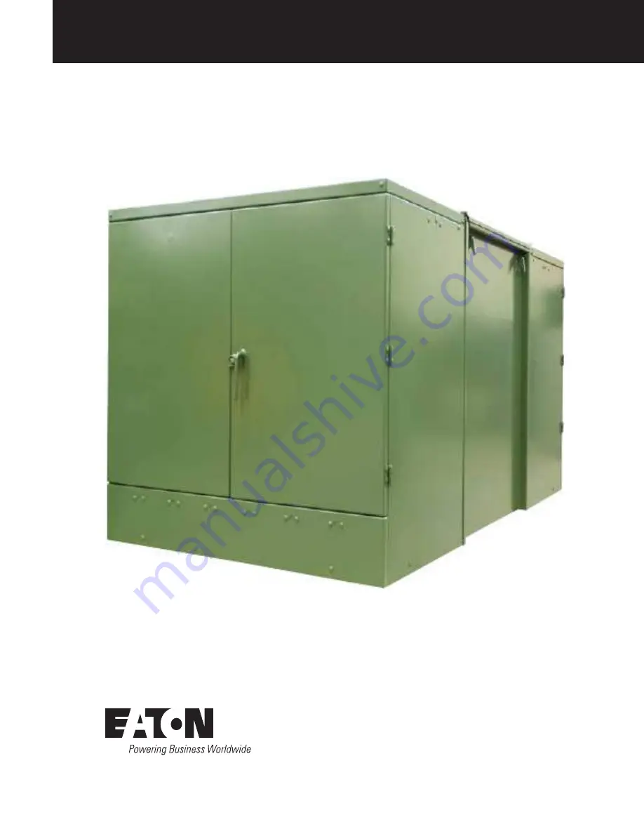
Field Service Instructions: Replacement of Cover Gasket for
Padmount Switchgear Side-Hinge-2 Models
COOPER POWER
SERIES
Padmount Switchgear
MN285009EN
Effective April 2019Supercedes February 2017
Page 1: ...Field Service Instructions Replacement of Cover Gasket for Padmount Switchgear Side Hinge 2 Models COOPER POWER SERIES Padmount Switchgear MN285009EN Effective April 2019 Supercedes February 2017...
Page 2: ...PURPOSE OR MERCHANTABILITY OTHER THAN THOSE SPECIFICALLY SET OUT IN ANY EXISTING CONTRACT BETWEEN THE PARTIES ANY SUCH CONTRACT STATES THE ENTIRE OBLIGATION OF EATON THE CONTENTS OF THIS DOCUMENT SHAL...
Page 3: ...ITCHGEAR APPARATUS FUNCTIONAL TEST 4 3 IF APPLICABLE REMOVE THE CABLE CABINETS 6 4 REMOVE THE SIDE COVER NUT GUARDS 7 5 REMOVE THE COVER FASTENERS 7 6 REMOVE THE COVER 8 7 REMOVE THE COVER GASKETS 8 8...
Page 4: ...nently hazardous situation which if not avoided will result in death or serious injury WARNING Indicates a potentially hazardous situation which if not avoided could result in death or serious injury...
Page 5: ...000 9 16 inch impact socket Figure 4 10 inch flat screwdriver Figure 5 Small aluminum bronze hammer Figure 6 3 inch putty knife flexible scraper Figure 7 12 to 18 inch extra long taper single end alig...
Page 6: ...9 16 inch impact socket Figure 5 10 inch flat screwdriver Figure 6 Small aluminum bronze hammer Figure 7 3 inch putty knife flexible scraper Figure 8 Proto J2120 aligning bar Figure 9 Hand wire brush...
Page 7: ...page 1 are available Check the ambient temperature conditions at the work site Cover gasket installation should be performed only at temperatures above 32 F 0 C Contact the factory if service is requi...
Page 8: ...nterior of the tank Figure 18 Dove tail joint 2 Perform the Switchgear Apparatus Functional Test Note N Consult factory service if the apparatus does not perform as expected during the functional test...
Page 9: ...receptacle For a three handle single way Push the momentary push buttons for each A B and C phase on the Tripper Box to individually trip these phases For a single handle 3 Way Push the B momentary p...
Page 10: ...corner 3 1 Remove the base clips fastening the cabinet to the concrete pad Figure 27 Figure 27 3 2 Remove all control cable connectors and braided ground leads Figure 28 Store the connectors and leads...
Page 11: ...or replacement later Figure 34 5 Remove the cover fasteners 5 1 Using a 9 16 inch socket on a right angle electric driver tool remove the silicon bronze nuts and Belleville washers from all cover bolt...
Page 12: ...2 18 32 35 57 40 24 43 54 89 47 18 39 49 94 62 18 58 63 171 70 24 58 89 274 74 24 46 126 233 84 24 53 142 297 94 28 46 179 289 104 24 46 173 317 6 3 Prepare to remove the cover 6 3 1 Make the necessar...
Page 13: ...shape is rectangular you will alternate short and long gaskets i e either short long short long or long short long short depending on your starting point Note N Once you apply the adhesive to a flang...
Page 14: ...e 47 9 3 4 Within 15 seconds after tamping Make any final adjustments to the gasket s position 9 4 Adhere a gasket to the second tank flange 9 4 1 Apply adhesive to the adjacent tank flange Note N App...
Page 15: ...o the gasket s position 10 Prepare the cover for reinstallation 10 1 Inspect the gasket mating area near the edges of the cover 10 1 1 Wipe all residual oil off of the gasket mating area 10 1 2 Clean...
Page 16: ...es in the following order First the four corners Next the center of each side Last all remaining holes Note N Use an IX 577 alignment bar altered Proto J2120 aligning bar or equivalent to align the ho...
Page 17: ...the remaining pattern below 1 3 4 2 8 6 7 5 Figure 59 11 5 2 Torque each set of hardware a second time using the pattern shown below 2 4 1 3 Figure 60 12 Perform a leak test 12 1 Connect the leak test...
Page 18: ...equalized slowly re open the ball valve to bring the pressure back to 7 25 psig Then shut off the valve 12 4 Let the tank sit for 30 minutes with the starting air pressure at 7 25 psig 12 5 After wai...
Page 19: ...close the shut off valve b Let the tank sit for 30 minutes with the air pressure at 7 25 psig then check to see if the pressure was maintained If the pressure dropped below 7 25 psig The tank is still...
Page 20: ...e cover Nut Guards into position on both sides of the main unit Figure 72 Figure 72 14 2 Install fasteners on both upper corners of the face plate Figure 73 Figure 73 14 3 Replace the side cover Nut G...
Page 21: ...nstall the base clips fastening the cabinet to the concrete pad Figure 77 Figure 77 15 6 Repeat step 15 1 through step 15 5 to reinstall the cabinet on the opposite side of the unit 16 Repeat the Swit...
Page 22: ...18 Replacement of Cover Gasket for Padmount Switchgear Side Hinge 2 Models Field Service Instructions MN285009EN April 2019 This page is intentionally left blank T...
Page 23: ...19 Replacement of Cover Gasket for Padmount Switchgear Side Hinge 2 Models Field Service Instructions MN285009EN April 2019 This page is intentionally left blank T...
Page 24: ...d States Eaton com cooperpowerseries 2019 Eaton All Rights Reserved Printed in USA Publication No MN285009EN Rev 02 April 2019 Eaton is a registered trademark All trademarks are property of their resp...