


TX140 S2
Upgrade and Maintenance Manual
45
Basic hardware procedures
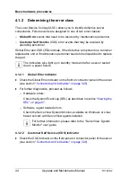
4.1.3
Locating the defective component
After determining the error class by the CSS or Global Error indicators (see
section
"Determining the error class" on page 44
) local diagnostic indicators on
the front panel, system board, HDD modules and power supply units allow you
to identify the defective component (see section
"Connectors and indicators" on
page 320
).
I
For further information, refer to the "ServerView Suite Local Service
Concept (LSC)" manual.
4.1.3.1
Local diagnostic indicators on the front
Ê
Check the CSS indicator on the front and connector panels of the server.
I
In addition to local diagnostic indicators, CSS or Global Error LEDs
indicate, if the defective component is a customer or field replaceable
unit (see section
"Determining the error class" on page 44
).
4.1.3.2
Local diagnostic indicators on the system board
Using the Indicate CSS button
Ê
Shut down and power off the server.
Ê
Disconnect the AC power cord from the system.
I
It is mandatory to disconnect power cords in order to use the Indicate
CSS functionality.
Ê
Press the Indicate CSS button to highlight defective components (see
section
"Onboard indicators and controls" on page 322
).
I
In addition to local diagnostic indicators, CSS or Global Error LEDs
indicate, if the defective component is a customer replaceable unit or if a
service technician needs to be dispatched to replace the part (see
section
"Determining the error class" on page 44
).
If the system has been powered off to replace a non hot-plug unit, a
system of PRIMERGY diagnostics indicators guides you to the faulty
component.
Summary of Contents for PRIMERGY TX140 S2
Page 30: ...30 Upgrade and Maintenance Manual TX140 S2 Before you start ...
Page 98: ...98 Upgrade and Maintenance Manual TX140 S2 Basic software procedures ...
Page 120: ...120 Upgrade and Maintenance Manual TX140 S2 Power supply ...
Page 148: ...148 Upgrade and Maintenance Manual TX140 S2 Hard disk drives solid state drives ...
Page 158: ...158 Upgrade and Maintenance Manual TX140 S2 System fan and air duct ...
Page 208: ...208 Upgrade and Maintenance Manual TX140 S2 Expansion cards and backup units ...
Page 216: ...216 Upgrade and Maintenance Manual TX140 S2 Main memory ...
Page 314: ...314 Upgrade and Maintenance Manual TX140 S2 Cabling ...
Page 332: ...332 Upgrade and Maintenance Manual TX140 S2 Appendix ...