


320
Upgrade and Maintenance Manual
TX140
S2
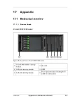
Appendix
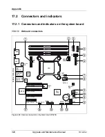
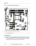
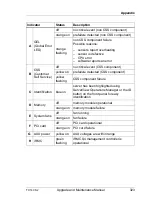
17.2 Connectors and indicators
17.2.1 Connectors and indicators on the system board
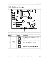
17.2.1.1 Onboard connectors
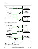
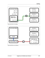
Figure 224: Internal connectors of system board D3239
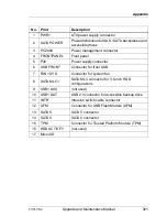
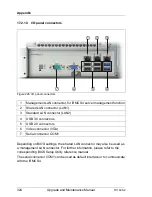
External connectors
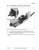
Slot 3 PCIe x8
MLC
SATA1-4
Battery
DIMM1B
Indicate
CSS
CPU
SATA6
SATA
POWER
PWR1
HDD ACTIVITY
Intrusion
TPM
Slot 2 PCIe x4
Management
LAN/
USB 9/10
Shared LAN/
USB 7/8
Standard LAN/
USB 5/6
USB Front
Slot 4 PCIe x8
Slot 1 PCIe x1
Intel
C224
USB1
DAT
USB1AUX
iRMC S4
FAN1
SYS
UFM
DIMM2B
DIMM1A
DIMM2A
COM1
VGA
SATA5
Intel
i210
Intel
i217
Jumper
PC2009
P30
Frontpanel
Service
LAN
Micro
SD
Summary of Contents for PRIMERGY TX140 S2
Page 30: ...30 Upgrade and Maintenance Manual TX140 S2 Before you start ...
Page 98: ...98 Upgrade and Maintenance Manual TX140 S2 Basic software procedures ...
Page 120: ...120 Upgrade and Maintenance Manual TX140 S2 Power supply ...
Page 148: ...148 Upgrade and Maintenance Manual TX140 S2 Hard disk drives solid state drives ...
Page 158: ...158 Upgrade and Maintenance Manual TX140 S2 System fan and air duct ...
Page 208: ...208 Upgrade and Maintenance Manual TX140 S2 Expansion cards and backup units ...
Page 216: ...216 Upgrade and Maintenance Manual TX140 S2 Main memory ...
Page 314: ...314 Upgrade and Maintenance Manual TX140 S2 Cabling ...
Page 332: ...332 Upgrade and Maintenance Manual TX140 S2 Appendix ...