background image

36

2.2

Pre-work preparations

CAUTION

1

Complete the "A Product information sheet" (

J

pg.54).

2

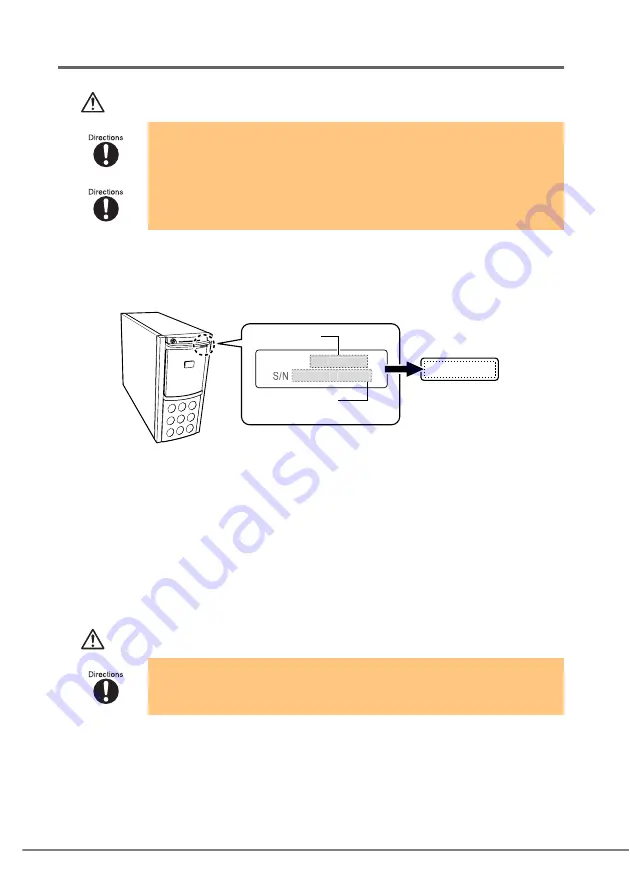
Copy the information on "Product ID and manufactures number 
label" attached to the server to the supplied blank label.

3

Shut down the system after checking the server system operation.

Make sure that the system is operating properly before performing the conversion to 
rackmount type.

4

Turn off the server and disconnect the power cable from the 
server.

5

If any peripherals are connected to the server, turn off all 
peripherals and disconnect them.

CAUTION

• For safety reasons, make sure the server is located on a stable and level surface 

when performing the conversion as the combined weight can be 29kg.

• Also, work in an open space as the rackmount must be laid horizontally to 

perform the conversion.

• Devices inside the server remain hot after shutdown. Wait for approximately 10 

minutes after shutdown before installing or removing hardware options from the 
server.

MODEL  

PG

XXXXXX

ST

XXX

A

XXXXX

Product ID

Manufactures 
number

* "

X

" indicates A to Z or 0 to 9

Copy the information 

in this blank label

Summary of Contents for PRIMERGY PG-R1CK21

Page 1: ...ラックについて サーバを搭載できるラックには 3 つのタイプがあります 以下のラック以外にはサーバ を搭載することができませんので ご注意ください スタンダードラック 型名 PG R6RC1 PG R6RC2 PG R4RC1 PG R4RC2 PG R4RC3 PG R4RC4 PG R3RC1 PG R3RC2 スリムラック 型名 GP5 R1RC6 GP5 R1RC7 GP5 R2RC3 GP5 R2RC4 16U ラック 型名 PG R5RC2 安全にお使いいただくために 本書には 本製品を安全に正しくお使いいただくための重要な情報が記載されています 本製品をお使いになる前に 本書を熟読してください 特に 本書の 安全上のご注意 をよくお読みにな り 理解された上で本製品をお使いください また本書は 本製品の使用中にいつでもご覧になれるよう大切に保管してください スタンダードラック...

Page 2: ...次のように表記しています の箇所のように文字間隔を空けて表記している部分は Space キーを 1 回押してく ださい 使用する OS が Windows または MS DOS の場合は コマンド入力を英大文字 英小文 字のどちらで入力してもかまいません ご使用の環境によって が と表示される場合があります CD ROM ドライブのドライブ名を CD ROM ドライブ で表記しています 入力の際 は お使いの環境に合わせて ドライブ名を入力してください CD ROM ドライブ setup exe 警告 この表示を無視して 誤った取り扱いをすると 人が死亡する可能性 または重傷を負う可能性があることを示しています 注意 この表示を無視して 誤った取り扱いをすると 人が損害を負う可能 性があること および物的損害のみが発生する可能性があることを示 しています で示した記号は 警告 注意を促す内...

Page 3: ...インテルコーポレーションの 商標または登録商標です その他の会社名および製品名は 各社の商標または登録商標です All Rights Reserved Copyright FUJITSU LIMITED 2006 記号 意味 お使いになる際の注意点や してはいけないことを記述しています 必ずお読みください ハードウェアやソフトウェアを正しく動作させるために必要なことが 書いてあります 必ずお読みください 参照ページや参照マニュアルを示しています 製品名称 本文中の表記 PRIMERGY TX150 S5 ラックマウント変換機構 ラックマウント変換機構 本製品 PRIMERGY TX150 S5 サーバ本体 本サーバ タイプ 本文中の表記 据え置きタイプ タワータイプ ラックに搭載するタイプ ラックマウントタイプ ...

Page 4: ...ントタイプへの変換作業は 安定した場所で行ってくださ い オプションの搭載によって 最大 29kg の重量となりますので十分注意して ください サーバのラックマウントタイプへの変換作業は サーバ本体を横にして作業を するのに十分な広さの場所で行ってください 電源を切った直後は サーバの内部の装置が熱くなっています 内蔵オプショ ンの取り付けや取り外しを行う場合は 電源を切ったあと 10 分ほど待ってか ら 作業を始めてください ラックの開口部 通風孔など をふさがないでください 通風孔をふさぐと内 部に熱がこもり 火災の原因となります 電源ケーブルおよび各種ケーブル類に足がひっかかる場所には設置しないでく ださい 故障の原因となります 空気の吸排気口である装置前面部および背面部をふさがないでください これ らをふさぐと内部に熱がこもり 火災の原因となります サーバ本体を移動する場合は 必ず...

Page 5: ...ハードディスクユニットの取り外し 10 3 2 タワータイプの各カバー取り外し 12 3 3 オペレータパネルと 5 インチストレージベイの入れ替え 14 3 4 ラックマウントタイプの各カバー取り付け 17 3 5 サーバ本体のラックへの搭載 19 3 6 内蔵ハードディスクユニットの取り付け 23 3 7 ラック搭載後の周辺装置接続 24 3 8 型名号機ラベルの貼り付け 24 4 作業後の操作 25 4 1 周辺機器 電源ケーブルの接続 25 4 2 電源を入れる前の確認 25 4 3 Chassis ID の更新 26 付録 A 使用環境シート 27 ...

Page 6: ...る以下の部品がすべてそろっているかどうかを確 認してください 万一 足りない部品があった場合は担当営業員に連絡してください 部品 スライドレール レールブラケットを含む 左右 1 組 ラックフロントカバー 1 枚 フロントカバー 1 枚 M5 サラネジ 8 個 M4 サラネジ 4 個 M3 サラネジ 4 個 M4 タップタイトネジ 8 個 ワッシャー 8 個 M5 ラックナット 4 個 フロントカバーブラケット 2 個 型名号機ラベル 1 枚 㪲Ꮐ㪴 㪲ฝ㪴 ...

Page 7: ...J 1 梱包物の確認 7 CPU ラベル 1 枚 Pentium D プロセッサ用 CPU ラベル 1 枚 Celeron D プロセッサ用 CPU ラベル 1 枚 Xeon プロセッサ用 TX150 S5 搭載用テンプレート 部品 ...

Page 8: ...8 2 作業を始める前に 変換作業の流れと 作業前の準備について説明します 2 1 作業の流れ ...

Page 9: ...システムの動作状 況を確認してください 4 サーバ本体の電源を切り 電源ケーブルをサーバ本体から取り外します 5 周辺機器が接続されている場合は 周辺機器の電源を切り サーバ本体か らすべて取り外します 注意 サーバのラックマウントタイプへの変換作業は 安定した場所で行ってくださ い オプションの搭載によって 最大 29kg の重量となりますので十分注意して ください サーバのラックマウントタイプへの変換作業は サーバ本体を横にして作業を するのに十分な広さの場所で行ってください 電源を切った直後は サーバの内部の装置が熱くなっています 内蔵オプショ ンの取り付けや取り外しを行う場合は 電源を切ったあと 10 分ほど待ってか ら 作業を始めてください S N PG XXXXXX ST XXX A XXXXX ဳฬ ㅧ ภ ઃ䈱ဳฬภᯏ䊤䊔䊦 䋨 䋩䈮ᦠ䈐౮䈚䉁䈜䇯 ...

Page 10: ...トタイプに変換後は 必ず取り外し前と同じ位置 に搭載してください サーバ本体を移動する前に 必ず内蔵ハードディスクユニットを取り外してく ださい 内蔵ハードディスクユニットに衝撃が加わると 保存されているデー タが損傷することがあります 電源を切った直後は サーバの内部の装置が熱くなっています 内蔵オプショ ンの取り付けや取り外しを行う場合は 電源を切ったあと 10 分ほど待ってか ら 作業を始めてください 䌛䉺䊪䊷䉺䉟䊒ᤨ䈱ᱜ㕙䌝 䌛䊤䉾䉪䊙䉡䊮䊃䉺䉟䊒ᤨ䈱ᱜ㕙䌝 ʣɮ º Óìïô Îõíâåò ʣɮ º Óìïô Îõíâåò ʣɮ º Óìïô Îõíâåò ʣɮ º Óìïô Îõíâåò ʣɮ º ÓÃÓÉ ÉÄ ʣɮ º ÓÃÓÉ ÉÄ µ ʣɮ º ÃÄ ÒÏÍ ÄÖÄ ÒÁÍ ÆÄÄ ʣɮ º Óìïô Îõíâåò ʣɮ º Óìïô Îõíâåò ʣɮ º Óìïô ...

Page 11: ...人体の静電気を放電します 4 内蔵ハードディスクユニットを取り外します 内蔵ハードディスクユニット前面のタブ を押しながらハンドルを上側に開け 手前に引きます 引き出す ときは 内蔵ハードディスクユニットに 手を添え 両手で持って引き出してくだ さい 3 5 インチストレージベイのダミーユニット は取り外す必要はありません そのまま ラックマウントタイプに変換できます ドライブカバーキーは装置ごとに異なります 紛失 しないように注意してください 紛失した場合は ロック部を破壊する必要があり 部品の有償交換となりますので ドライブカバー キーの管理については十分ご注意ください なお 万一ドライブカバーキーを紛失された場合は 担当 営業員までご連絡ください 䊄䊤䉟䊑䉦䊋䊷䉨䊷 䊊䊮䊄䊦 ...

Page 12: ...12 3 2 タワータイプの各カバー取り外し 左サイドカバー フロントカバー 右サイドカバーを取り外します 注意 左サイドカバーの取り外し 1 サーバ本体背面側 2ヵ所の M3 ネジを取り外します 2 サーバ背面側にゆっくりとスライドさせながら 手前に倒して取り 外します カバーや内蔵オプションを取り扱う場合には サーバ本体の金属部分に触れて 人体の静電気を放電してください ...

Page 13: ...載 13 J フロントカバーの取り外し 1 サーバ本体左側 3 箇所のタブを外した後 右側 2 箇所のタブを押しなが ら 手前に引いて取り外します 右サイドカバーの取り外し 1 サーバ本体背面側 2ヵ所の M3 ネジを取り外します 2 ドライバなどを使って右サイドカバーのタブを外し サーバ後方に スライドさせて取り外します サイドカバーの上面を抑えながら ゆっくりとサーバ後方にスライドさ せてください Ꮐ 䉺䊑 ฝ 䉺䊑 䉺䊑 ...

Page 14: ...イの入れ替え ラックマウントタイプに変換するときは 5 インチストレージベイに搭載されているユ ニットおよびオペレータパネルを 以下の図のように向きを変えて入れ替えます サーバ固定足の取り外し 1 サーバ本体を図のように横にして置き サーバ固定足を固定しているネジ 3 箇所 を取り外します 2 サーバ固定足のプレートごと背面側にスライドさせ 手前に引いて 取り外します 䇼ᄌ ೨䇽 䇼ᄌ ᓟ䇽 䉥䊕䊧䊷䉺䊌䊈䊦 5䉟䊮䉼䉴䊃䊧䊷䉳䊔䉟 CD ROM䊄䊤䉟䊑 ...

Page 15: ...し引き出します 両側のツメを内側に押しながら ゆっくりと 手前に引きます 2 オペレータパネル上面のコネクタから オペレータパネルのケーブル 2 本を取 り外します 3 本体内部の 5 インチ内蔵オプションと CD ROM ドライブの各コネクタか ら 内部ケーブル 電源ケーブルをそれぞれ取り外します 4 オペレータパネル 5 インチ内蔵オプション ダミーユニット CD ROM ドライブを 5 インチストレージベイから取り外します 両側のツメを内側に押しながら ゆっくりと 手前に引きます 䉿䊜 䇼䉥䊕䊧䊷䉺䊌䊈䊦 㕙䇽 䉿䊜 ...

Page 16: ...向きに置いてください 2 取り外したオペレータパネルを取り付けます 半分ほど差し込んだら オペレータ パネル上面のコネクタに 元通りに ケーブルを接続してください その後 カチッと音がするところま で押し込んでください 3 5 インチ内蔵オプション ダミーユニット CD ROM ドライブを取り付 けます カチッと音がするところまで押し込 んでください 注意 4 CD ROM ドライブに 内部ケーブルおよび電源ケーブルを接続します 5 5 インチ内蔵オプションに 内部ケーブルおよび電源ケーブルを接続します 各ドライブやダミーユニットを取り付けるときは ケーブル類をサー バ本体の部品にはさみ込まないように注意してください ...

Page 17: ... の M4 タップタイトネジで 固定してください 2 フロントカバーをサーバ本体正面から取り付けます 先に下部 2 箇所のタブをはめ込んで から 上部 3 箇所のタブをはめ込ん で取り付けてください 左サイドカバーの取り付け 左サイドカバーは 3 2 タワータイプの各カバー取り外し P 12 と逆の手順で取り 付けてください 注意 左サイドカバーを取り付ける前に 搭載している拡張カードがスロットの奥まで完 全に差し込まれているかどうか確認してください ラックマウントタイプへの変換 作業の衝撃などでカードの差し込みがゆるむ場合があります 左サイドカバーを取り付ける前に サーバ本体内部に不要な部品や工具を置き 忘れないように注意してください 左側面 ネジ穴 ㇱ䈱䉺䊑 ਅㇱ䈱䉺䊑 ...

Page 18: ...ラックフロントカバーを取り付けます 両側のフラントカバーブラケット に 添付の M4 タップタイトネジ 4 本で固定します 2 ラックフロントカバーに 添付の CPU ラベルを貼り付けます 取り外したタワータイプのフロント カバー P 13 に貼り付けられて いる CPU ラベルの種類を確認し 同じものを添付品 P 7 の中か ら探して右図の位置に貼ります このとき ラベルとフロントカバー の両端をそろえてください 䉕䈠䉐䈋䉎 䊤䊔䊦 5mm ...

Page 19: ...付け位置確認 1 ラックのフロントドアとリアドアを開けます 2 サーバ本体を取り付ける位置を決めます ラック支柱の穴の間隔が狭い位置にサーバ底面 がくるように合わせます スライドレールの取り付け 1 M5 ラックナットをラックに取り付けます 1 台の筐体につき 5U 使用します サーバ本体を取り付ける位置の下か ら 2 個目と 14 個目の位置に ラック 支柱の内側からツメを引っ掛けて取 り付けます 同梱の TX150 S5 搭載 用テンプレートを使用してください 䌛䊤䉾䉪ᡰᩇ䌝 䉰䊷䊋ᧄ ᐩ㕙䈱 䌛䊤䉾䉪ᡰᩇ೨㕙䌝 5U䋨ᧄ ⵝ 䉰䉟䉵䋩 䉰䊷䊋ᧄ ᐩ㕙䈱 䇭14 䋨M5䊤䉾䉪䊅䉾䊃䋩 䇭2 䋨M5䊤䉾䉪䊅䉾䊃䋩 ...

Page 20: ...レールを引き伸 ばし レールブラケットを M4 サラネジ 2 本 で固定し ます 3 スライドレールをラックに取り付けます 背面側から先に取り付けます 背面側の取 り付け穴 2 個目 にレールの突起部分を 差し込んで ワッシャーと M5 サラネジで 1 個目と 3 個目の位置を固定してください 同様に前面側も固定します 䊧䊷䊦䊑䊤䉬䉾䊃 䉴䊤䉟䊄䊧䊷䊦 M4䉰䊤䊈䉳 1 ᓟ䉐 䈱䊈䉳ⓣ ೨䈎䉌3 䈱䊈䉳ⓣ 䈖䈖䈮䊈䉳ⓣ䈏 䈋䉎 䉁䈪ᒁ䈐િ䈳䈜 ㇱಽ 䌛 㕙 䌝 M5䉰䊤䊈䉳 䊪䉾䉲䊞䊷 䌛೨㕙 䌝 ...

Page 21: ...溝 にインナーレールの突起部分 が収まるように サーバ本体 を上から差し込みます 2 取り付けたインナーレールの ネジ穴とサーバ本体側面のネ ジ穴が合う位置まで サーバ 本体を後方へ押し込みます 3 M3 サラネジでしっかりと固定 します 両側各 2 箇所を固定します 3 サーバ本体を後方へスライドさせて ラックに搭載します スライドレール両側のロックを 矢印方向に押しながら ゆっく りと後方へスライドさせて搭載 します 注意 サーバ本体をスライドさせる場合や元に戻す場合は 指や衣服がはさ まれないよう注意してください けがをするおそれがあります 䉟䊮䊅䊷䊧䊷䊦 䌛䉰䊷䊋ᧄ 䌝 䌛䊧䊷䊦䌝 M3䉰䊤䊈䉳䈪 ቯ䋨ਔ 䋩 䈕䈩 㒰 ...

Page 22: ...22 4 サーバ本体とラックを固定します サーバ本体とラックを M5 つまみネ ジ 4 本で固定します ラックにサーバおよび周辺装置が搭載されていない場合には ラックに添付のブ ランクパネルを取り付けてください M5䈧䉁䉂䊈䉳 ...

Page 23: ...ィスクユニットの取り付け 注意 1 内蔵ハードディスクユニットのハンドルを出した状態で 内蔵ハードディ スクベイに差し込みます 2 内蔵ハードディスクユニットのハンドルを倒して 確実に差し込みます 3 すべての内蔵ハードディスクユニットを取り付けます 内蔵ハードディスクユニットは 取り外したときと同じ位置に必ず取り付けて ください 取り付け位置が違うと正しく動作しないおそれがあります 取り付け後 奥まで完全に差し込まれているかどうかを確認してください 䊊䊮䊄䊦 ...

Page 24: ...ちることを防止するため 電源ケーブルをサーバ本体に接続したあと 下図 を参考にして 添付のリリースタイで換気孔と電源ケーブルのコネクタから 10cm くらい の箇所を固定してください なお 電源ケーブルを抜くときは 必ず本体側の電源コネクタを抜くようにしてください 3 8 型名号機ラベルの貼り付け 2 2 作業前の準備 P 9 で記載した 型名号機ラベル を サーバ本体の下図の位置 に貼り付けてください 型名と製造番号は 本サーバの故障などが発生し 修理相談窓口へご連絡の際にお 伝えいただく必要があります 必ず所定の位置に貼り付けてください 䊥䊥䊷䉴䉺䉟 వ 䉕ㅢ䈚䇮 䈵䈦䈴䈦䈩 ቯ䈜䉎 MODEL S N PG XXXXXX ST XXX A XXXXX ဳฬ ㅧ ภ ...

Page 25: ...電源を入れる前の確認 サーバに電源を入れる前に 必ず次のことを確認してください 内蔵ハードディスクユニットについて ケーブルについて 拡張カードについて 周辺機器について 確認事項 確認 3 5 インチストレージベイの奥まで完全に差し込まれていますか すべての内蔵ハードディスクユニットが取り付けられていますか 確認事項 確認 正しく接続されていますか 各ドライブのコネクタに完全に差し込まれていますか 電源を入れる前に取り外しておく必要があるケーブルは 取り外してありま すか サーバ本体の電源ケーブルは接続されていますか 確認事項 確認 拡張カードはスロットの奥まで完全に差し込まれていますか 変換作業時の衝撃でカードの差し込みがゆるむ場合があります 確認事項 確認 変換作業前に取り外した周辺機器は 正しく接続されていますか ...

Page 26: ...ロンプトが表示されたら 次のコマンドを入力し Enter キー を押します A SMT rackch BAT 正常に処理が行われると 以下のように表示されます 5 フロッピーディスクを取り出し サーバ本体の電源を切ります Server Management Tools ディスクを入れてシステムを起動する前に ServerView の OS ブート監視 機能が無効に設定されていることを確認してくだ さい 初期設定は無効です OS ブート監視 機能が有効の状態でシステムを起 動すると 本サーバが自動的に電源切断や再起動するなど 意図しない動作をする おそれがあります OS ブート監視 機能を有効にして運用している場合は 設定終了後 運用を再開 する前に 再度本機能を有効にしてください ServerView の詳細については ServerView ユーザーズガイド を参照してください Chass...

Page 27: ...情報を記入しておきます この使用環境シートは担当営業員または修理相談窓口への連絡時に必要となりますので なくさないようにご注意ください ࠨ ࡃ ࠢဳฬ PRIMERGY ࡕ ฬ ဳฬ ࠪ ࠕ ภ Product Key㧔 㧕 ࠢࡑ ࡦ ޓޓ ᄌ ᯏ ဳฬ PG ޓޓޓޓ 㧙 ޓޓޓޓ 㧙 ޓޓޓޓ 㧙 㧕ࠨ ࡃᧄ ߩᏀฝߤߜࠄ߆ߩ 㕙ߦProduct Key ࡌ ߇ ޓ ઃߐࠇߡ ࠆ႐วߩߺ ߒߡߊߛߐ ޕ TX150 S5 PG R1CK21 ...

Page 28: ...GY TX150 S5 Rack Conversion Kit November 2006 Rack cabinet types This kit can be installed in the following rack cabinets For safety use Important information to use this product safely and correctly has been described in this manual Please peruse this manual before using this product Use this product after often reading Safety of this manual and being understood especially Keep this manual carefu...

Page 29: ...splayed in the following way In the areas of the mark press the Space key once When using Windows or DOS OS commands are not case sensitive CD ROM drive name are shown as CD ROM drive Enter your drive name according to your environment CD ROM Drive setup exe WARNING Ignoring this symbol could be potentiality lethal CAUTION Ignoring this symbol may lead to injury and or damage the server or hardwar...

Page 30: ...of their respective companies All Rights Reserved Copyright FUJITSU LIMITED 2006 Symbols Meaning These sections explain prohibited actions and points to note when using this device Make sure to read these sections These sections explain information needed to operate the hardware and software properly Make sure to read these sections This mark indicates reference pages or manuals Product name Expre...

Page 31: ...e sure the server is located on a stable and level surface when performing the conversion work as the combined weight can be 29kg Also work in an open space as the rackmount must be laid horizontally to perform the conversion Devices inside the server remain hot after shutdown Wait for approximately 10 minutes after shutdown before installing or removing hardware options from the server Do not obs...

Page 32: ... 41 3 4 Attaching the covers to a rackmount type 44 3 5 Installing the server in the rack 46 3 6 Reinstalling the hard disk units 50 3 7 Connecting peripheral devices after installing the server in the rack cabinet 51 3 8 Labeling a server with product ID and manufactures number 51 4 After rackmount conversion 52 4 1 Reconnecting peripheral devices and the power cable 52 4 2 Before turning on the ...

Page 33: ...ion kit before performing operations If any items are missing contact an office listed in the B Contact Information Jpg 55 Item Slide rail 1 pair Rack front cover 1 Front cover 1 M5 flathead screw 8 M4 flathead screw 4 M3 flathead screw 4 M4 tap tight screw 8 Washer 8 M5 rack nut 4 Front cover bracket 2 Blank label 1 Left Right ...

Page 34: ...34 CPU label 1 Pentium D Processor CPU label 1 Celeron D Processor CPU label 1 Xeon Processor Item ...

Page 35: ...s 2 1 Workflow Remove the hard disk units Pre work preparations Remove the covers from a tower type Reposition the operator panel and 5 inch storage bays Attach the covers to a rackmount type Install the server in the rack Reinstall the hard disk units After conversion Check various items before turning on the power Update the chassis ID ...

Page 36: ...5 If any peripherals are connected to the server turn off all peripherals and disconnect them CAUTION For safety reasons make sure the server is located on a stable and level surface when performing the conversion as the combined weight can be 29kg Also work in an open space as the rackmount must be laid horizontally to perform the conversion Devices inside the server remain hot after shutdown Wai...

Page 37: ... note of the bay numbers and slot numbers for each hard disk unit so that they can be reinstalled to their proper locations Before moving the server remove all hard disk units Striking or hitting a hard disk unit can corrupt its data Devices inside the server remain hot after shutdown Wait for approximately 10 minutes after shutdown before installing or removing hardware options from the server Ba...

Page 38: ...lease button on the hard disk unit raise the handle upward to release the lock and pull out to remove Hold the hard disk unit with both your hands and pull it out It is not necessary to remove dummy units for 3 5 inch storage bays The server can be converted to a rackmount type with the bays attached The drive cover key is unique to each device Be careful not to lose this key If you lose the drive...

Page 39: ...right side covers CAUTION Removing the left side cover 1 Remove the M3 screws of two places at the rear side 2 Slowly slide the side cover to the rear side and then tilt it toward you to remove it from the server Before handling the covers or any hardware options first touch the metal chassis to discharge static electricity ...

Page 40: ...pressing the right tabs Removing the right side cover 1 Remove the M3 screws of two places at the rear side 2 Release the tab using a tool such as screw driver and slide the right side cover to the rear of the server to remove it Hold the top of the server and slide the right side cover to the rear of the server Left tabs Right tabs Tab ...

Page 41: ...st reorient the operator panel and 5 inch storage bay components as follows Removing the fixation feet 1 Horizontally knock down and put the server And then detach the screw in three places where the foot of the server is fixed 2 Move the plate to the rear of the server Then pull forward and detach it Operator panel 5 inch storage bay CD ROM drive Before After ...

Page 42: ...nect the two cables from the top of the operator panel 3 Disconnect the internal and power cables from the 5 inch hardware options and CD ROM drive 4 Remove the operator panel CD ROM drive all 5 inch hardware options and or dummy units from their bays Pull out each option slowly towards you with its latches being pressed inward Latches Top view of operator panel Latches ...

Page 43: ...he removed operator panel Insert the operator panel halfway reconnect the cables and push the panel until it clicks 3 Reinstall all 5 inch hardware options dummy units and CD ROM drive Insert all 5 inch hardware options dummy units and CD ROM drive and push them until they click CAUTION 4 Reconnect the internal and power cables to the CD ROM drive 5 Reconnect the internal and power cables to 5 inc...

Page 44: ... tabs first Afterwards insert upper three tabs Reattaching the left side cover Reverse the procedure in 3 2 Removing the covers from a tower type Jpg 39 to reattach the left side cover to the server CAUTION Make sure that all expansion cards are properly inserted in their slots before reattaching the left side cover Some expansion cards may have become loose while performing the conversion Before ...

Page 45: ...4 tap tight screws of included items 2 Paste CPU label of included items to the rack front cover Examine the kind of CPU label pasted to the front cover used by the tower type Jpg 40 Then Looking for the same label from included items Jpg 34 paste it to the same position as illustration Paste CPU label according to the edge of the frame of the front cover CPU label 5mm Arrange the edge ...

Page 46: ...height at which to place the server in the rack by aligning the base of the server with one of the narrower spaces in the rack bracket Attaching the slide rails 1 Attach M5 rack nuts to the rack Use 5U per device Insert the latches of the rack nuts from the inside of the rack bracket into 2nd and 14th holes counting from the position where the server is installed to attach the rack nuts Rack brack...

Page 47: ...een 3 Attach the slide rails to the rack Attach the rear side first fix by inserting the ledge part of the rail bracket in the 2nd hole and using the M5 flathead screws and washers at the 1st and 3rd hole And then fix the front side in the same way M4 flathead screws Slide rail Rail bracket Extend the rail until the screw hole comes to be seen at this position The last screw hole The third screw h...

Page 48: ...rew hole on the server side 3 Fix the inner rail and the server with the M3 flathead screws Fix each side with two screws 3 Slide the server backward to install it in the rack cabinet Hold the locks on the right and left of the slide rail pressed and slide the server even further into the rack CAUTION Be careful not to pinch your fingers or catch any clothing when sliding the server into the cabin...

Page 49: ...r and installing to the rack 49 E 4 Secure the server to the rack Secure the server to the rack with the 4 M5 thumbscrews Mount the blank panel to secure the rack in the part where the device is not installed M5 thumbscrews ...

Page 50: ...2 Close the handle to lock the hard disk units in their storage bays 3 Reinstall all hard disk units Be sure to reinstall the hard disk units to their correct bays from which they were removed Hard disk units installed in wrong bays may not operate correctly Make sure that all hard disk units are properly inserted in their bays Handle ...

Page 51: ...e supplied release tie that passed clamp the rear of the server When plugging off the cable make sure to unplug the connector at the server end 3 8 Labeling a server with product ID and manufactures number Attach the Product ID and manufactures number label that you filled in according to 2 2 Pre work preparations Jpg 36 Product ID and manufactures number may be required when you contact an office...

Page 52: ...re turning on the server Internal hard disk units Cables Expansion cards Peripheral devices Item Check Are they all the way seated in the 3 5 inch storage bay Are all internal hard disk units installed Item Check Is each cable connected correctly Is each cable properly seated in the corresponding drive Did you disconnect cables required to do so before turning on the power Is the server power cabl...

Page 53: ...r The following message appears when the processing is properly executed 5 Eject the floppy disk from the drive and turn off the server Before starting the system from the Server Management Tools disk check to see that the OS Boot Monitoring function of ServerView is disabled default setting If the system is started with the OS Boot Monitoring function enabled the server is liable to automatically...

Page 54: ...s sheet as you must provide this information when you contact your maintenance engineer Server Rack Model PRIMERGY Name Product ID Serial number Product Key Rack Conversion Kit Type PG TX150 S5 PG R1CK21 Record the product key if there is a product key label a ffixed on either side of the server ...

Page 55: ...oor No 3505 Jalan Technokrat 5 63000 Cyberjaya Selangor Darul Ehsan Malaysia Philippines Fujitsu Philippines Inc Tel 63 2 812 4001 Fax 63 2 817 7576 Address 2nd Floor United Life Building A Arnaiz Legaspi Village Makati Metro Manila Philippines Singapore Fujitsu Asia Pte Ltd Tel 65 6777 6577 Fax 65 6771 5502 Address 20 Science Park Road 03 01 TeleTech Park Singapore Science Park II Singapore 11767...

Page 56: ...for damages to third party copyrights or other rights arising from the use of any information in this manual No part of this manual may be reproduced in any form without the prior written permission of Fujitsu PRIMERGY TX150 S5 ラックマウント変換機構 PG R1CK21 取扱説明書 Rack Conversion Kit PG R1CK21 User s Guide B7FY 1901 01 00 発 行 日 発行責任 2006 年 11 月 富士通株式会社 Issued on Issued by November 2006 FUJITSU LIMITED ...

Reviews: