1
1. Checking the Delivered Product
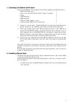
Before using the MB2198-161-E, confirm that the following components are included in the box:
•
LQFP-144P Header type 9*
1
: 1
•
Screws for securing the header board (M2
×
10mm, 0.4mm pitch)
: 4
•
Washer
: 4
•
NQPACK144SE*
2
: 1
•
HQPACK144SE*
3
: 1
•
Operation manual (Japanese version)
: 1
•
Operation manual (English version, this manual)
: 1
*1 : Referred to as "header board". A YQPACK144SE-4W (manufactured by Tokyo Eletech Cor-
poration, referred to as the “YQPACK” in this manual) is mounted on the header board.
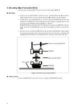
*2 : The IC socket (manufactured by Tokyo Eletech Corporation, referred to as the “NQPACK” in
this manual). The NQPACK includes a specialized screw driver and 3 guide pins. A more re-
liable compatible socket, the NQPACK144SE-SL (sold separately; manufactured by Tokyo
Eletech Corporation), can be used by making a screw hole in the user system board for affixing
the IC socket. For more information, contact Tokyo Eletech Corporation.
*3 : The IC socket cover (manufactured by Tokyo Eletech Corporation, referred to as the “HQ-
PACK” in this manual). The Includes 4 screws (M2
×
6mm, 0.4mm pitch) for attaching the HQ-
PACK.
This product can function as an adapter unit when used in combination with an adapter board (sold
separately). The product can also function as an emulator system when used in conjunction with an
emulator.
For details about the emulators and adapter boards that support this product, contact our Sales De-
partment or Support Department.
2. Handling Precautions
The adapter unit is precision-manufactured to improve dimensional accuracy and to ensure reliable
contact, and is therefore mechanically weak.
Take the following precautions to ensure that the header board is always used correctly in an appro-
priate environment.
•
Avoid placing any stress on the NQPACK that is mounted on the user system while the adapter
unit is connected.
Summary of Contents for MB2147-01
Page 10: ......
Page 11: ...FUJITSU LIMITED DSU FR EMULATOR MB2198 01 HARDWARE MANUAL ...
Page 12: ......
Page 20: ...viii ...
Page 22: ...x ...
Page 56: ...34 CHAPTER 2 CONNECTION METHOD ...
Page 64: ...42 CHAPTER 3 OPERATION METHOD ...
Page 66: ......
Page 76: ...54 APPENDIX B User System Specifications ...
Page 78: ......
Page 92: ......

