12
CHAPTER 1 PRODUCT HANDLING AND SPECIFICATIONS
■
Operation Overview
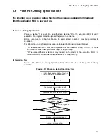
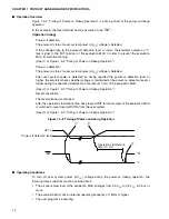
Figure 1.9-2 "Timing of Power-on Debug Operation" is a timing chart of the power-on debug
operation.
In this example, the reset terminal name is assumed to be "INIT".
[Operation timing]
Power-off detection:
The power-off status of user system power (UV
CC
) voltage is detected.
If the voltage drops to the power-off detection level or lower, the emulator outputs an "L"
level signal to the INIT terminal of the evaluation MCU in order to prevent the evaluation
MCU from malfunctioning.
(See (1) of Figure 1.9-2 "Timing of Power-on Debug Operation".)
Power-on detection:
The power-on status of user system power (UV
CC
) voltage is detected.
After user system power is detected as having reached the power-on detection level or
higher, the emulator checks whether voltage is maintained at the power-on detection level or
higher during the operation stabilization time (about 10 ms) of the evaluation MCU.
(See (2) of Figure 1.9-2 "Timing of Power-on Debug Operation".)
Reset cancellation:
The reset terminal is controlled.
After the operation stabilization time has elapsed, INIT terminal output of the evaluation MCU
is switched to reset input (xRSTIN) from the user system.
(See (3) of Figure 1.9-2 "Timing of Power-on Debug Operation".)
Figure 1.9-2 Timing of Power-on Debug Operation
■
Operating Conditions
To turn off user system power (UV
CC
) voltage during the power-on debug operation, the
following three conditions must be satisfied at all:
•
The all user power level of the evaluation MCU changes from 0.9 V
CC
to 0.5 V
CC
in 25
µ
s or
more.
•
The evaluation MCU has an internal operating frequency of 1 MHz or higher.
•
The user program is executing.
UV
CC
INIT
"H"
"L"
Power-off detection level
Operation stabilization
time (10 ms)
Summary of Contents for MB2147-01
Page 10: ......
Page 11: ...FUJITSU LIMITED DSU FR EMULATOR MB2198 01 HARDWARE MANUAL ...
Page 12: ......
Page 20: ...viii ...
Page 22: ...x ...
Page 56: ...34 CHAPTER 2 CONNECTION METHOD ...
Page 64: ...42 CHAPTER 3 OPERATION METHOD ...
Page 66: ......
Page 76: ...54 APPENDIX B User System Specifications ...
Page 78: ......
Page 92: ......


