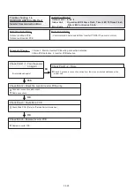
Discharge Temp Sensor Error
OK
OK
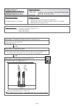
DC
CN141
TH
E
R
M
IS
TO
R
(C
O
M
P
S
H
E
LL
)
<
TH
10
>
TH
ER
M
IS
TO
R
(D
IS
.T
EM
P
)
<
TH
1
>
B
LA
C
K
B
LA
C
K
B
LA
C
K
B
LA
C
K
1 2
3 4 5 6
1 2
3 4 5 6
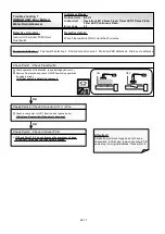
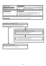
Discharge temperature thermistor 1
Discharge temperature thermistor 1 short detected
Discharge thermistor 1 open detected after compressor 1 operated
continuously for 5 minutes or more
1. Connector connection defective, open
2. Thermistor defective
3. Main PCB defective
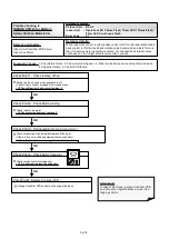
Check Point 1 : Check the connector connection and cable open
Connector connection state check
Cable open check
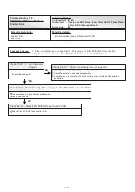
Check Point 2 : Check the thermistor
Thermistor characteristics check (Disconnect the thermistor from the PCB and check.)
* For the thermistor characteristics, refer to the "Service Parts Information 22".
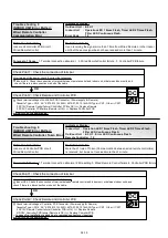
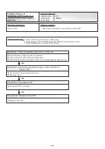
Check Point 3 : Check voltage of Main PCB (DC5.0V)
Main PCB (CN141:1-2) voltage value = 5V
Remove the thermistor from Main PCB, check the voltage.
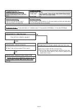
If the voltage does not appear, replace Main PCB and set up orignal address.
Discharge temperature sensor 1 (CN141:1-2)
Indoor Unit : Operation LED 9 times Flash, Timer LED 15 Times Flash,
Filter LED Continuous Flash.
Outdoor Unit : E. 71. 1
Error Code : 71
04-31
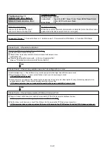
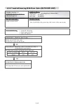
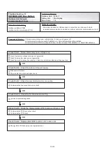
Trouble shooting 21
Indicate or Display:
Detective Actuators:
Detective details:
OUTDOOR UNIT Error Method:
Forecast of Cause :
Summary of Contents for Airstage J-II
Page 1: ...Small VRF system for light commercial and home use SERVICE MANUAL ...
Page 2: ......
Page 6: ......
Page 7: ...1 TEST RUN ...
Page 8: ......
Page 27: ...2 OUTDOOR UNIT OPERATION CONTROL ...
Page 28: ......
Page 42: ......
Page 43: ...3 INDOOR UNIT OPERATION ...
Page 44: ......
Page 63: ...4 TROUBLE SHOOTING ...
Page 73: ......
Page 170: ......
Page 171: ...5 APPENDING DATA UNIT ...
Page 172: ......
Page 174: ...MODELS AUXB07 AUXB09 AUXB12 AUXB14 AUXB18 AUXB24 05 02 5 2 WIRING DIAGRAM 5 2 1 Indoor Unit ...
Page 175: ...MODELS AUXD18 AUXD24 AUXA30 AUXA36 AUXA45 AUXA54 05 03 ...
Page 176: ...MODELS ARXB07 ARXB09 ARXB12 ARXB14 ARXB18 05 04 ...
Page 177: ...MODEL ARXB24 MODELS ARXB30 ARXB36 05 05 ...
Page 178: ...MODEL ARXB45 05 06 ...
Page 179: ...MODEL ARXA24 MODELS ARXA30 ARXA36 ARXA45 05 07 ...
Page 180: ...MODELS ARXC36 ARXC45 ARXC60 MODELS ARXC72 ARXC90 05 08 ...
Page 181: ...MODELS ARXD07 ARXD09 ARXD12 ARXD14 ARXD18 ARXD24 05 09 ...
Page 182: ...MODELS AB A12 AB A14 AB A18 AB A24 05 10 ...
Page 183: ...MODELS AB A12LBTH AB A14LBTH 05 11 AB A18LBTH AB A24LBTH ...
Page 184: ...05 12 MODELS AB A30 AB A36 AB A45 AB A54 ...
Page 185: ...05 13 MODELS AB A30LBTH AB A36LBTH AB A45LBTH AB A54LBTH ...
Page 186: ...MODELS AS A07 AS A09 AS A12 AS A14 05 14 ...
Page 187: ...MODELS AS E07 AS E09 AS E12 AS E14 05 15 ...
Page 188: ...MODELS AS A18 AS A24 AS A30 05 16 ...
Page 189: ...05 17 MODELS AS A18LACH AS A24LACH AS A30LACH ...
Page 190: ...05 18 MODELS AJ A36 45 54LALH 5 2 2 Outdoor Unit ...
Page 195: ...6 DISASSEMBLY PROCESS ...
Page 196: ......

