03-13
2
1
3
4
3-7-2 Group Remote Controller
UTY - CGG
WEEKLY TIMER
Different schedules can be set for each day of the week.
Four timers can be set for each day.
Operation on/off time, operation mode, and temperature can be specified for each timer.
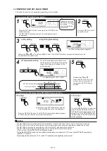
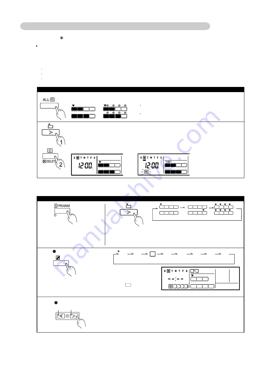
1. WEEKLY TIMER
The timer function is not available depending on the initial setting.
Note: When a time is not set, the weekly timer cannot be started.
Different schedules can be set for each day of the week.
Four timers can be set for each day
Press the ALL TIMER button to start or cancel the WEEKLY timers for all indoor units.
If any of the indoor units are in the timer mode, pressing this
button cancels the timers for all indoor units.
If none of the indoor units are in the timer mode, pressing
this button starts the timers for all indoor units.
Press the Select button to select the indoor unit.
Press the PROGRAM (CLOCK AD-
JUST) button.
* Do not press this button for two sec-
onds or more, otherwise you will en-
ter the time setting mode.
Press the Select button to select the indoor unit.
* If all indoor units are selected, the times for all of the registered indoor unit
timers are set at once.
Day of the week setting
S M T W T F S
ALL
All indoor units
SUN
MON
TUE
WED
THU
FRI
SAT
Press the Timer Mode (DELETE) button to start or cancel the WEEKLY timers.
The timer does not start if the time is not set.
Press the DAY button to select the day of the week.
* For ALL, all of the days can be set together when a appears around
each day.
To start / cancel the WEEKLY timer operation
To set the WEEKLY timer
Press the Set Time buttons to set the time in 10-minute increments.
* Hold down a Set Time button to adjust the time quickly.
* The time already set at another timer is skipped at the relevant indoor unit.
Decrement Increment
Timer setting
Summary of Contents for Airstage J-II
Page 1: ...Small VRF system for light commercial and home use SERVICE MANUAL ...
Page 2: ......
Page 6: ......
Page 7: ...1 TEST RUN ...
Page 8: ......
Page 27: ...2 OUTDOOR UNIT OPERATION CONTROL ...
Page 28: ......
Page 42: ......
Page 43: ...3 INDOOR UNIT OPERATION ...
Page 44: ......
Page 63: ...4 TROUBLE SHOOTING ...
Page 73: ......
Page 170: ......
Page 171: ...5 APPENDING DATA UNIT ...
Page 172: ......
Page 174: ...MODELS AUXB07 AUXB09 AUXB12 AUXB14 AUXB18 AUXB24 05 02 5 2 WIRING DIAGRAM 5 2 1 Indoor Unit ...
Page 175: ...MODELS AUXD18 AUXD24 AUXA30 AUXA36 AUXA45 AUXA54 05 03 ...
Page 176: ...MODELS ARXB07 ARXB09 ARXB12 ARXB14 ARXB18 05 04 ...
Page 177: ...MODEL ARXB24 MODELS ARXB30 ARXB36 05 05 ...
Page 178: ...MODEL ARXB45 05 06 ...
Page 179: ...MODEL ARXA24 MODELS ARXA30 ARXA36 ARXA45 05 07 ...
Page 180: ...MODELS ARXC36 ARXC45 ARXC60 MODELS ARXC72 ARXC90 05 08 ...
Page 181: ...MODELS ARXD07 ARXD09 ARXD12 ARXD14 ARXD18 ARXD24 05 09 ...
Page 182: ...MODELS AB A12 AB A14 AB A18 AB A24 05 10 ...
Page 183: ...MODELS AB A12LBTH AB A14LBTH 05 11 AB A18LBTH AB A24LBTH ...
Page 184: ...05 12 MODELS AB A30 AB A36 AB A45 AB A54 ...
Page 185: ...05 13 MODELS AB A30LBTH AB A36LBTH AB A45LBTH AB A54LBTH ...
Page 186: ...MODELS AS A07 AS A09 AS A12 AS A14 05 14 ...
Page 187: ...MODELS AS E07 AS E09 AS E12 AS E14 05 15 ...
Page 188: ...MODELS AS A18 AS A24 AS A30 05 16 ...
Page 189: ...05 17 MODELS AS A18LACH AS A24LACH AS A30LACH ...
Page 190: ...05 18 MODELS AJ A36 45 54LALH 5 2 2 Outdoor Unit ...
Page 195: ...6 DISASSEMBLY PROCESS ...
Page 196: ......


