3-4 ELECTRONIC EXPANSION VALVE CONTROL
03-09
3-5 DRAIN PUMP OPERATION
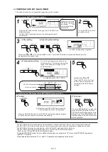
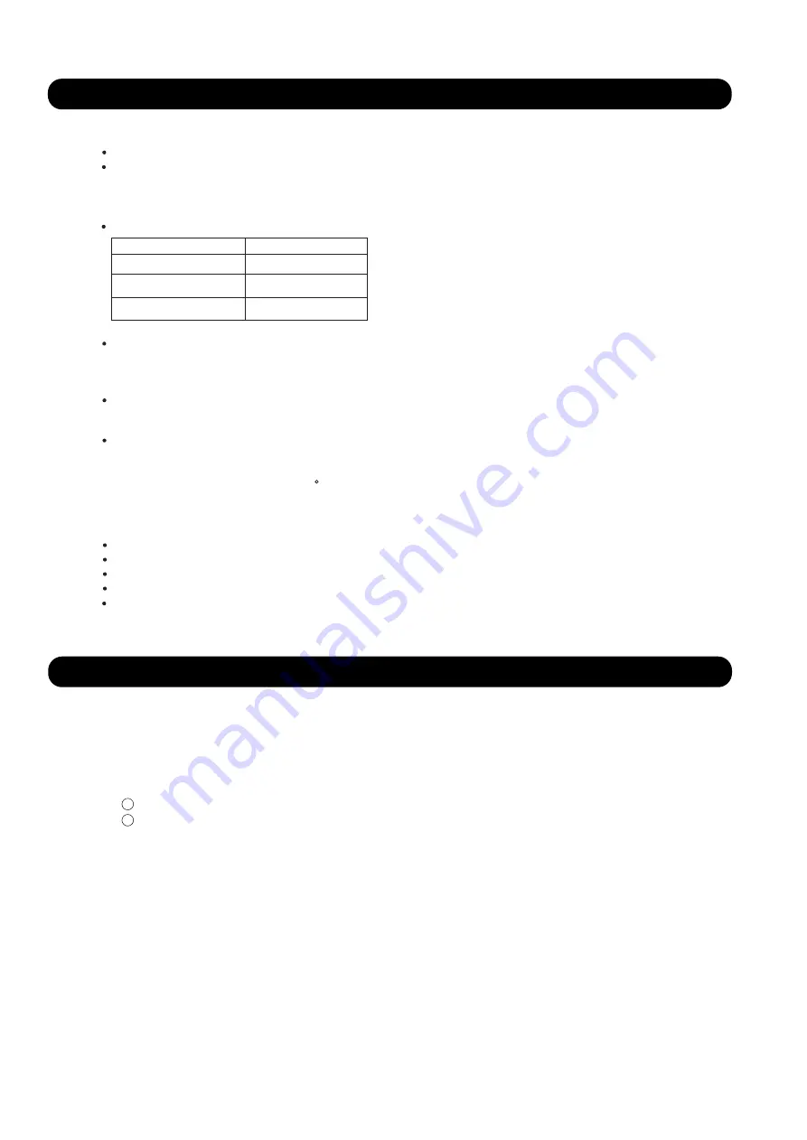
1. Initialization
2. Operation Control
When starting up
Automatic operatic control
Automatic PI control is performed based on the indoor unit heat exchanger outlet temp and inlet temp.
Room temperature control
The room temperature is controlled so that it reaches to the set-up temperature based on the difference
between the room temperature and the set-up temperature, and the change of indoor unit temperature.
if the room temperature becomes 0.5 C lower than the set-up temperature, EEV is fully closed.
3. Special Control
(1) When cooling and refrigerant circulation starts, the drain pump starts simultaneously.
(2) The drain pump operates continuously for 3 minutes after the refrigerant circulation stopped.
(3) When the refrigent circulation is stopped by a start of indoor heat exchanger frost prevention
operation, the drain pump will turn off in 1 hour after the end of indoor heat exchanger frost
prevention operation.
(4) When the water level in the drain pan rises up and then the float switch functions:
Microcomputer stops the refrigerant circulation and indoor fan motor operation.
Drain pump operates continuously for 3 minutes after the float switch is turned off.
(Almost condensing water may be drained)
(5) When the float switch turns ON continuously for 3 minutes, 'FAILURE INDICATION' operates.
(6) When the float switch turns OFF within 3 minutes, the unit starts cooling operation.
1
2
When the power is turned ON.
When it has passed the limited time since the last initialization.
When indoor unit stopping
Oil recovery operation : Controlled pulse.
Test run operation : Controlled pulse.
Icing protection control : Fully closed.
Pump down operation : Fully open.
Defrost operation : Controlled pulse
Outdoor unit Condition
EEV Condition
Cooling
Heating
Fully closed
Slightly open
(Cooling) Move to the cooling control base pulse in steps.
(Heating) Move to the heating control base pulse in steps.
OFF
Fully closed
Summary of Contents for Airstage J-II
Page 1: ...Small VRF system for light commercial and home use SERVICE MANUAL ...
Page 2: ......
Page 6: ......
Page 7: ...1 TEST RUN ...
Page 8: ......
Page 27: ...2 OUTDOOR UNIT OPERATION CONTROL ...
Page 28: ......
Page 42: ......
Page 43: ...3 INDOOR UNIT OPERATION ...
Page 44: ......
Page 63: ...4 TROUBLE SHOOTING ...
Page 73: ......
Page 170: ......
Page 171: ...5 APPENDING DATA UNIT ...
Page 172: ......
Page 174: ...MODELS AUXB07 AUXB09 AUXB12 AUXB14 AUXB18 AUXB24 05 02 5 2 WIRING DIAGRAM 5 2 1 Indoor Unit ...
Page 175: ...MODELS AUXD18 AUXD24 AUXA30 AUXA36 AUXA45 AUXA54 05 03 ...
Page 176: ...MODELS ARXB07 ARXB09 ARXB12 ARXB14 ARXB18 05 04 ...
Page 177: ...MODEL ARXB24 MODELS ARXB30 ARXB36 05 05 ...
Page 178: ...MODEL ARXB45 05 06 ...
Page 179: ...MODEL ARXA24 MODELS ARXA30 ARXA36 ARXA45 05 07 ...
Page 180: ...MODELS ARXC36 ARXC45 ARXC60 MODELS ARXC72 ARXC90 05 08 ...
Page 181: ...MODELS ARXD07 ARXD09 ARXD12 ARXD14 ARXD18 ARXD24 05 09 ...
Page 182: ...MODELS AB A12 AB A14 AB A18 AB A24 05 10 ...
Page 183: ...MODELS AB A12LBTH AB A14LBTH 05 11 AB A18LBTH AB A24LBTH ...
Page 184: ...05 12 MODELS AB A30 AB A36 AB A45 AB A54 ...
Page 185: ...05 13 MODELS AB A30LBTH AB A36LBTH AB A45LBTH AB A54LBTH ...
Page 186: ...MODELS AS A07 AS A09 AS A12 AS A14 05 14 ...
Page 187: ...MODELS AS E07 AS E09 AS E12 AS E14 05 15 ...
Page 188: ...MODELS AS A18 AS A24 AS A30 05 16 ...
Page 189: ...05 17 MODELS AS A18LACH AS A24LACH AS A30LACH ...
Page 190: ...05 18 MODELS AJ A36 45 54LALH 5 2 2 Outdoor Unit ...
Page 195: ...6 DISASSEMBLY PROCESS ...
Page 196: ......


