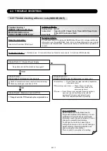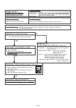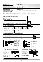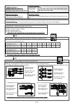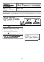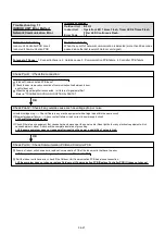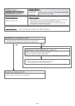
Trouble shooting 8
INDOOR UNIT Error Method:
Indoor Unit Fan Motor Error
Indicate or Display:
Indoor Unit : Operation LED 5 times Flash, Timer LED 1 Times Flash,
Filter LED Continuous Flash.
Outdoor Unit : E.5 U.1
Error Code : 5 1
Detective Actuators:
Indoor Unit Controller PCB Circuit
Indoor Fan Motor
Detective details:
When Indoor fan control is either phase control or DC control and rotation feed
back control is ON, the feed back rotation value becomes 0 and lasts for more
than 1 minute at motor operation condition. Or, the feed back rotation value
continues at 1/3 of target value for more than 1 minute.
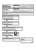
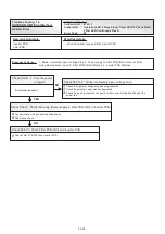
Check Point 2 : Check Motor winding
Check Indoor Fan motor
>>If Fan motor is abnormal, replace it.
Check Point 1 : Check rotation of Fan
Rotate the fan by hand when operation is off.
(Check if fan is caught, dropped off or locked motor)
>>If Fan or Bearing is abnormal, replace it.
Check Point 3 : Check ambient temp. around motor
Check excessively high temperature around the motor.
(If there is any surrounding equipment that causes heat)
>>Upon the temperature coming down, restart operation..
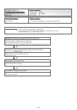
Check Point 4 : Check Motor Capacitor
Check continuity of motor capacitor
>>If it is shorted, replace the capacitor.
Check Point 5 : Replace Controller PCB
OK
OK
OK
OK
Forecast of Cause :
1. Fan rotation failure 2. Fan motor winding open 3. Motor protection by surrounding temp. increase
4. Capacitor failure 5. Control PCB failure
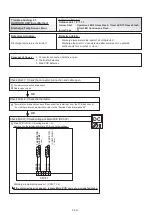
Attention!!
In case of Duct type, replace Controller PCB
and set up the original address, since it is a
tapping control.
Change Controller PCB and set up the original address.
04-18
Summary of Contents for Airstage J-II
Page 1: ...Small VRF system for light commercial and home use SERVICE MANUAL ...
Page 2: ......
Page 6: ......
Page 7: ...1 TEST RUN ...
Page 8: ......
Page 27: ...2 OUTDOOR UNIT OPERATION CONTROL ...
Page 28: ......
Page 42: ......
Page 43: ...3 INDOOR UNIT OPERATION ...
Page 44: ......
Page 63: ...4 TROUBLE SHOOTING ...
Page 73: ......
Page 170: ......
Page 171: ...5 APPENDING DATA UNIT ...
Page 172: ......
Page 174: ...MODELS AUXB07 AUXB09 AUXB12 AUXB14 AUXB18 AUXB24 05 02 5 2 WIRING DIAGRAM 5 2 1 Indoor Unit ...
Page 175: ...MODELS AUXD18 AUXD24 AUXA30 AUXA36 AUXA45 AUXA54 05 03 ...
Page 176: ...MODELS ARXB07 ARXB09 ARXB12 ARXB14 ARXB18 05 04 ...
Page 177: ...MODEL ARXB24 MODELS ARXB30 ARXB36 05 05 ...
Page 178: ...MODEL ARXB45 05 06 ...
Page 179: ...MODEL ARXA24 MODELS ARXA30 ARXA36 ARXA45 05 07 ...
Page 180: ...MODELS ARXC36 ARXC45 ARXC60 MODELS ARXC72 ARXC90 05 08 ...
Page 181: ...MODELS ARXD07 ARXD09 ARXD12 ARXD14 ARXD18 ARXD24 05 09 ...
Page 182: ...MODELS AB A12 AB A14 AB A18 AB A24 05 10 ...
Page 183: ...MODELS AB A12LBTH AB A14LBTH 05 11 AB A18LBTH AB A24LBTH ...
Page 184: ...05 12 MODELS AB A30 AB A36 AB A45 AB A54 ...
Page 185: ...05 13 MODELS AB A30LBTH AB A36LBTH AB A45LBTH AB A54LBTH ...
Page 186: ...MODELS AS A07 AS A09 AS A12 AS A14 05 14 ...
Page 187: ...MODELS AS E07 AS E09 AS E12 AS E14 05 15 ...
Page 188: ...MODELS AS A18 AS A24 AS A30 05 16 ...
Page 189: ...05 17 MODELS AS A18LACH AS A24LACH AS A30LACH ...
Page 190: ...05 18 MODELS AJ A36 45 54LALH 5 2 2 Outdoor Unit ...
Page 195: ...6 DISASSEMBLY PROCESS ...
Page 196: ......


