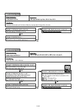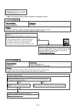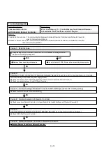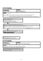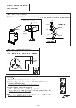
Indoor / Outdoor Unit Error
Error Code display [ 5 U ]
Other controls are left as they are.
Condition of occurrence : When error occurred on Indoor/Outdoor unit that is connected to Network Convertor.
Release condition : When the error of Indoor/Outdoor unit that is connected to Network Convertor is released.
Cause 1 : Error occurred in Indoor unit
Refer to Indoor Unit trouble shooting.
(Removal of error of indoor unit connected to network converter)
Cause 2 : Error occurred in Outdoor unit
Refer to Outdoor Unit trouble shooting.
(Removal of error of outdoor unit connected to network converter)
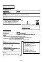
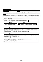
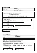
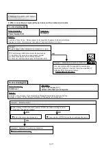
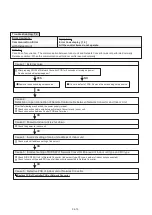
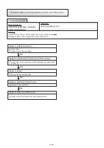
Software Error
Error Code display [ C A ]
All the control items do not operate.
Other Controls are left they are.
Details :
Condition of occurrence : Micon program performed an abnormal control.
Error of inside information of EEPROM.
initial setting of Network Converor PCB was not normally performed.
Release condition : Micon has been reset, and the control of Network Convertor became normal.
When error disappeared and Network Convetor becomes available to control.
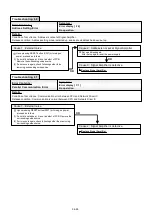
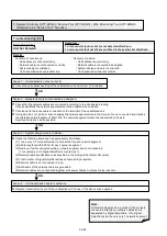
Cause 1 : External noise
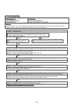
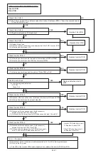
Check continuation of error.
(1) If error is released automatically, it is not a defect of PCB. Remove the surrounding noise source around Network Convertor.
(2) If error is not released automatically, check followings.
After pressing SW104 of Network Convertor PCB for 5 seconds or turning on power.
Does error code display reappear?
OK
YES
OK
It is not a defect of PCB. Remove the surrounding noise source.
Remove the surrounding noise source.
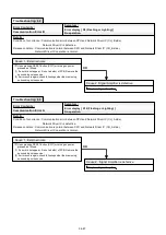
Cause 2 : Network Convertor is defective.
Replace Network Convertor.
04-75
Error Contents :
Symptom :
Trouble shooting 74
Error Contents :
Symptom :
Trouble shooting 75
OK
NO
Details :
Summary of Contents for Airstage J-II
Page 1: ...Small VRF system for light commercial and home use SERVICE MANUAL ...
Page 2: ......
Page 6: ......
Page 7: ...1 TEST RUN ...
Page 8: ......
Page 27: ...2 OUTDOOR UNIT OPERATION CONTROL ...
Page 28: ......
Page 42: ......
Page 43: ...3 INDOOR UNIT OPERATION ...
Page 44: ......
Page 63: ...4 TROUBLE SHOOTING ...
Page 73: ......
Page 170: ......
Page 171: ...5 APPENDING DATA UNIT ...
Page 172: ......
Page 174: ...MODELS AUXB07 AUXB09 AUXB12 AUXB14 AUXB18 AUXB24 05 02 5 2 WIRING DIAGRAM 5 2 1 Indoor Unit ...
Page 175: ...MODELS AUXD18 AUXD24 AUXA30 AUXA36 AUXA45 AUXA54 05 03 ...
Page 176: ...MODELS ARXB07 ARXB09 ARXB12 ARXB14 ARXB18 05 04 ...
Page 177: ...MODEL ARXB24 MODELS ARXB30 ARXB36 05 05 ...
Page 178: ...MODEL ARXB45 05 06 ...
Page 179: ...MODEL ARXA24 MODELS ARXA30 ARXA36 ARXA45 05 07 ...
Page 180: ...MODELS ARXC36 ARXC45 ARXC60 MODELS ARXC72 ARXC90 05 08 ...
Page 181: ...MODELS ARXD07 ARXD09 ARXD12 ARXD14 ARXD18 ARXD24 05 09 ...
Page 182: ...MODELS AB A12 AB A14 AB A18 AB A24 05 10 ...
Page 183: ...MODELS AB A12LBTH AB A14LBTH 05 11 AB A18LBTH AB A24LBTH ...
Page 184: ...05 12 MODELS AB A30 AB A36 AB A45 AB A54 ...
Page 185: ...05 13 MODELS AB A30LBTH AB A36LBTH AB A45LBTH AB A54LBTH ...
Page 186: ...MODELS AS A07 AS A09 AS A12 AS A14 05 14 ...
Page 187: ...MODELS AS E07 AS E09 AS E12 AS E14 05 15 ...
Page 188: ...MODELS AS A18 AS A24 AS A30 05 16 ...
Page 189: ...05 17 MODELS AS A18LACH AS A24LACH AS A30LACH ...
Page 190: ...05 18 MODELS AJ A36 45 54LALH 5 2 2 Outdoor Unit ...
Page 195: ...6 DISASSEMBLY PROCESS ...
Page 196: ......


