background image


23 


Chapter5  

Display 


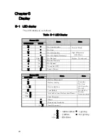
5-1   LED display 

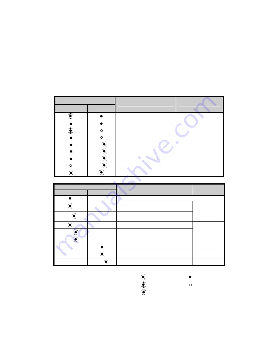
The LED display is as follows. 

Table  5-1 LED Display 

Status LED 

OPERATION

MODE 

State 

Note 


On-Line standby 


On-Line 

Normal Mode 


On-HE standby 


On-HE (High Effeciency) 

High Effeciency 

  (HE) Mode 


On-Battery 

Byzzer : 2s interval 


Bypass Standby 


On-Bypass   


Converter OFF   


Power-Down 


Status LED


BATTERY 

ALARM 

State 

Note 


Battery Disconnect 


Battery testing 

Standby 
On-Line 


Service Battery 

HE Standby 
On-HE 


Low Battery 


Just befire Low Battery shut Down 

On-Battery 
Buzzer: 
Synchronized 


Fast Charging 


Allarm 


Bypass not Available 


Input Abnormal 


2s 

2s 

2s 

0.5s 

:1sBlink(Blink)

2s 

:2sBlink 

0.5s 

:0.5sBlink 

:Lighting 

:UnLighting

2s 

0.5s 

0.5s 

2s 

Summary of Contents for PEN102J1C

Page 1: ...User s Manual Uninterruptible Power Supply Model PEN102J1C PEN102J1RT PEN152J1RT 15 PEN152J1RT PEN302J1RT 30 PEN302J1RT DN074 04 01 C...

Page 2: ...ries located in an SERVICE ACCESS AREA 1 Servicing of batteries should be performed or supervised by personnel knowledgeable about batteries and the required precautions 2 Risk of explosion if battery...

Page 3: ...een tested and found to comply with the limits for a Class A digital device pursuant to part 15 of the FCC Rules There limits are designed to provide reasonable protection against harmful interference...

Page 4: ...aged to try to correct the interference by one or more of the following measures Reorient or relocate the receiving antenna Increase the separation between the equipment and receiver Connect the equip...

Page 5: ...tion Show a pressing dangerous situation of causing death or a serious injury when not avoiding it Show a dangerous situation with a possibility of causing death or of a serious injury when not avoidi...

Page 6: ...ons content is shown in General compulsion Compulsion about earth Compulsion about cord Note The following signatures show note This symbol indicates that you should not discard the UPS or the UPS bat...

Page 7: ...Content and position of Warning Label Rack Tower Type The attention label becomes it as follows 1kVA VI WARNING...

Page 8: ...1 1kVA 1 5kVA VII...

Page 9: ...VIII 2 4kVA...

Page 10: ...3kVA IX...

Page 11: ...Tower Type The attention label becomes it as follows 1kVA X...

Page 12: ...e to assume the responsibility about the occurring damage Air and space appliance Equipment for transportation car train and ship etc Equipment for medical treatment Equipment for power generation con...

Page 13: ...when this device is used near the machine that controls remotely by the electric wave it might cause the malfunction of the equipment When this device is used by such an equipment measures such as ele...

Page 14: ...e electric shock Do not touch the input output terminal while energizing It is likely to get an electric shock Do not feel after the connecting cable by a wet hand It is likely to get an electric shoc...

Page 15: ...n Select the diameter of wire more than the device ratings current by the voltage standing 600V or more Do not put the foreign body Internal parts are short circuited when foreign bodies of metals and...

Page 16: ...gularly The battery shelf life shortens when the used temperature is 25 or more or there are a lot of electrical discharge frequencies and exchange it ahead of time Used temp Battery life expectancy B...

Page 17: ...ledge of electric work to do Follow the replacement procedure of the user s guide Remodeling and repair Because there is a high voltage part in this device The people other than the maintenance member...

Page 18: ...LCD display 25 Chapter Setting 27 Panel operating 28 Chapter Maintenance 41 Care 41 Storing 41 Battery exchange time 41 Battery exchange 42 Test of new battery 47 Recycling 47 Fuse exchange 47 Chapte...

Page 19: ......

Page 20: ...2RT 1 5kVA PEN152J1RT PEB048 2RT 2 4kVA PEN302J1RT 30 PEB072 2RT 3kVA PEN302J1RT PEB072 2RT EBM is constituted for increase when the backup is long necessary It introduces the feature of UPS that off...

Page 21: ...can be used as 19 inch rack installation or a tower installation The backup time can be extended by connecting EBM up to two until The load segment made a group can be started one by one and it interc...

Page 22: ...3 Chapter Part name and function UPS front Rack Tower Type Tower Type Figure 1 UPS front 1 2 3 4 5 6 7 8 9 10 11 11 10 11 12 1 2 5 6 9 3 4 7 8 12 1 3 4 10 2 10 5 6 7 8 9 10 1 2 3 4 6 7 8 9 11 11 5...

Page 23: ...Chnage content Item ON State of output 1s ON 1s OFF repeat State of no output 6 OPERATION LED OFF Converter OFF ON Normal OFF Hight Effeciency HE 0 5s ON 0 5s OFF repeat Battery 7 MODE LED 2s ON 2s O...

Page 24: ...only with same type and rating of fuse CAUTION 4 7 6 5 1 3 2 CAUTION See Installation Instructions before connecting to the supply For continued protection against risk of fire replace only with same...

Page 25: ...L5 30R 6 Load1 3k 5 15R x 1 and Terminal L Line N Nutral Earth 1k 5 15R x 2 1 1k 1 5k 5 15R x 3 7 Load2 2 4k 3k 5 15R x 1 8 Output Breaker1 2 4k 3k 15A for 5 15R Load1 9 Output Breaker2 2 4k 3k 15A f...

Page 26: ...following places Outdoor Place of direct sunshine Place of high temperature and humidity Recommendation 10 25 Place of strong vibration and strong impact Place where salinity and causticity gas are g...

Page 27: ...8 Figure 1 Need Space...

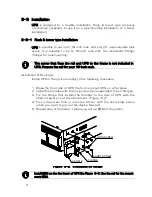
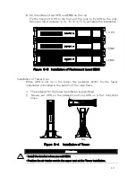
Page 28: ...rack Installation of Rack type Install UPS in the rack according to the following procedure 1 Make the front side of UPS the front and put UPS on a flat place 2 Install the handles with the long screw...

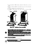
Page 29: ...stallation of Tower type When UPS is set up in the tower the pedestal plinth for the tower installation is installed in the bottom of the main flame 1 The pedestal for the tower installation is assemb...

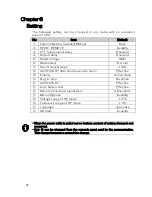
Page 30: ...arge time is influenced when not normally set Match in the operation form and set Shutdown timing of Power sol when EBM and power management software Power sol is additionally used When Power sol is u...

Page 31: ...tee becomes invalid Do not connect the large load of instant electric power Laser printer etc Ground the earth of the load with the rush current independently on the load side The output cable connect...

Page 32: ...oad side The output cable connected with the outlet with Plug Stop option can be fixed Do not push an output breaker pin The output of applicable Load stops Do not place a thing on the line of an outp...

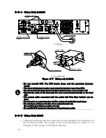
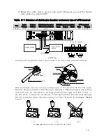
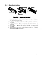
Page 33: ...ut on the back or the bottom of the TB cover Remove the round part of the TB cover and put it When removing the cutting lack side can be removed by strongly pushing the right and left i and several ti...

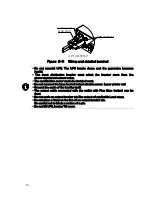
Page 34: ...do electrical work Do not connect the large load of instant electric power Laser printer etc Ground the earth of the load by itself The output cable connected with the outlet with Plug Stop option can...

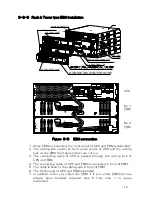
Page 35: ...and EBM is connected in front of EBM 5 The cable is fixed to the cable guide in front of EBM 6 The front panel of UPS and EBM is installed 7 In addition when you install one EBM it is put under EBM t...

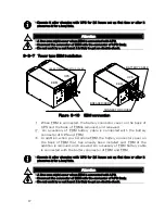
Page 36: ...ted with the battery connector of UPS and EBM In addition when you install one EBM the battery connector cover on the back of EBM that has already been installed and EBM of the addition is removed and...

Page 37: ...pass the cable through the window of a rear panel If used dry contact signal fix the cable to the terminal on the substrate Make the rail of the slot slide into the card edge and insert it up to the...

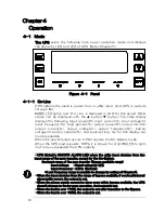
Page 38: ...ible When the power failure occurs UPS transfers the On Battery mode When the UPS load exceeds 100 it is shown for ALARM LED to light and to have exceeded the UPS capacity UPS blinks 1s ON OFF ALARM L...

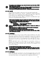
Page 39: ...output is cut after transition to On Bypass When the load is over 150 the output is cut If overload internal abnormality occurs the UPS transfer Bypass It transfers to the On Bypass once when the loa...

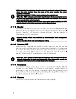
Page 40: ...s only schedule by communication from management software Bypass standby effects only manual bypass setting Converter OFF Converter OFF indicates the state to have turned off AC DC DC AC DC DC of UPS...

Page 41: ...er it is necessary to have done the charge for 12 hours or more The test is interrupted and the alarm is output when not agreeing with the condition or when events of the power failure and the alarm a...

Page 42: ...n Battery Byzzer 2s interval Bypass Standby On Bypass Converter OFF Power Down Status LED BATTERY ALARM State Note Battery Disconnect Battery testing Standby On Line Service Battery HE Standby On HE L...

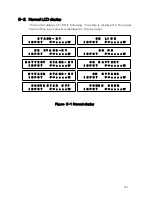
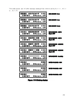
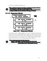
Page 43: ...layed in the the lower Figure 1 Normal display S T A N D B Y O N L I N E I N P U T I N P U T H E S T A N D B Y O N H E I N P U T I N P U T B A T T E R Y S T A N D B Y O N B A T T E R Y I N P U T I N P...

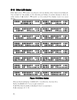
Page 44: ...F 1 0 0 E B M 1 R E P O O F F 1 0 0 S T A N D B Y I N P U T E B M 1 R E P O O F F 1 0 0 E B M 1 R E P O O F F 1 0 0 I N P U T V V I N P U T F H E B M 1 R E P O O F F 1 0 0 E B M 1 R E P O O F F 1 0 0...

Page 45: ...E B M 2 R E P O O F F 1 0 0 REPO REMOTE REPO I N P U T V V Signal OFF E B M 2 R E P O O N 1 0 0 REPO REMOTE REPO I N P U T V V Signal ON E B M 2 R M T O F F 1 0 0 REPO REMOTE REMOTE I N P U T V V Sig...

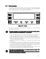
Page 46: ...UTOSTART after shutdown with alarm Effective Polarity Active close Buzzer stop No active AUTOSTART Effective Auto battery test Effective Remote shut down signal term 4 5seconds Manual Bypass Invalidit...

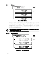
Page 47: ...t moves to the item that changes Push the SET button when you move to the item that changes The content of the item is displayed button button is pushed and it moves to the content that changes It is...

Page 48: ...to the EBM set item Set this when you increase EBM The deterioration of the battery is fast when using UPS without setting this Do not change initialization with EBM not increased REPO REMOTE Figure 3...

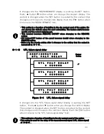
Page 49: ...the remote setting after it changes to the setting that the output is turned off at UTL failure signal delay Figure 4 UTL failure signal delay It changes into the UTL failure signal delay display in...

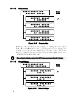
Page 50: ...Output delay item This setting is effective against the OFF button operation when On Battery Rated Voltage Figure 6 Rated Voltage C O N F I G U R A T I O N O U T P U T D E L A Y O U T P U T D E L A Y...

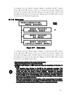
Page 51: ...E Intelligent mode ijudges a utility input and does the transfering of On Line On HE UPS transfers from On Line to On HE by the automatic operation The change from On HE to On Line when the input devi...

Page 52: ...he INV output outputs the frequency within this range The INV output outputs by the asynchronization at a utility input outside of this range The output is cut when there are an internal abnormality a...

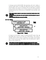
Page 53: ...ity When invalidity ON button recovery is Invalidity Polarity Figure 10 Polarity It changes into the Polarity display in pushing the SET button Push button button when you change the content display T...

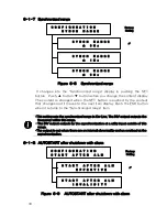
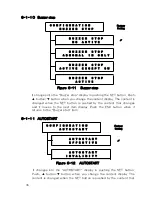
Page 54: ...UTOSTART It changes into the AUTOSTART display in pushing the SET button Push button button when you change the content display The content is changed when the SET button is pushed by the content that...

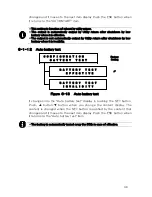
Page 55: ...uto battery test Figure 13 Auto battery test It changes into the Auto battery test display in pushing the SET button Push button button when you change the content display The content is changed when...

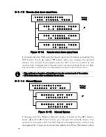
Page 56: ...uts down after confirming the set time Manual Bypass Figure 15 Manual Bypass It changes into the Manual Bypass display in pushing the SET button Push button button when you change the content display...

Page 57: ...ing the SET button Push button button when you change the content display The content is changed when the SET button is pushed by the content that changes and it moves to the next item display Push th...

Page 58: ...nge HE mode UPS transfer to On Battery with output cut of moment Intelligent mode UPS transfers to On Battery with output cut of moment And if possible On Line UPS transfers to On Line Language Figure...

Page 59: ...tton when you change the content display The content is changed when the SET button is pushed by the content that changes and it moves to the next item display Push the ESC button when it returns to t...

Page 60: ...e time When BATTERY LED of UPS blinks every two seconds it is time of the battery exchange It is necessary to exchange the batteries and Refer to the paragraph of Battery exchange The expectation time...

Page 61: ...tenance applicable to equipment and remote battery supplies not having a grounded supply circuit Internal battery exchange Attention Do the exchanging work by the person who has experience and knowled...

Page 62: ...BATTERY BRACKET SCREW OF FRONT PANEL FRONT PANEL SCREW BATTERY CONNECTOR OF UPS BATTERY CONNECTOR BATTERY BRACKET SCREW INTERNAL BATTERY FRONT PANEL SCREW OF FRONT PANEL CONNECTOR OF UPS BATTERY CONN...

Page 63: ...other than the following procedures Exchange EBM according to the following procedure 1 Do the EBM exchange by the mode other than the On Battery 2 The breaker on the rear of EBM is turned off 3 The f...

Page 64: ...an old battery are combined and used The longevity of the battery is influenced by an old battery and the expected life of a new battery shortens Make the UPS side a full charge about the exchange of...

Page 65: ...added it is more similar Above mentioned the cable from UPS becomes a cable from EBM The exchange of EBM becomes an exchange of not the internal battery exchange but EBM units Figure 4 Tower type EBM...

Page 66: ...disposed of properly For more information contact your local recycling reuse or hazardous waste center Attention Do not discard the waste electrical or electronic equipment WEEE in the trash For prope...

Page 67: ...sible to cooperate with the Power management Software Power SOL the Power Management software can exchange UPS and data by connecting the communications cable When abnormality occurs in the utility po...

Page 68: ...the remote shutdown function Network Agent Card Externals are shown in Figure 1 Figure 1 Network Agent Card 1 Network port The card communicates with the administrative terminal where power supply man...

Page 69: ...arm Reception 5V output 7 RTS Transmission RTS signal output 8 UTL failure Reception 5V output 9 RI Reception Wakeup on MODEM 1 The network agent card is displayed for the DCE by the signal name that...

Page 70: ...3 2 On Bypass output impossible Choose the ring tongue terminal of the size that suits M4 Cover and mount the sleeve on the ring tongue terminal Table 3 Terminal No Terminal Signal I O Spec Note REPO...

Page 71: ...on the output with a repeated ON button UPS shuts down by the REPO input when the On Battery The terminal REPO is a current of 10mA or less Choose the lock switch that corresponds to the ratings The...

Page 72: ...o the following procedure Connect it with the terminal REMOTE and the terminal GND by using twist or shield and size AWG 16 22 0 3mm2 1 3mm2 Because UPS is not stopped confirm the prepared lock switch...

Page 73: ...malfunction prevention This relay is turned on to the output status by the manual bypass Input abnormal When input abnormal is detected the UPS turns on relay contact of input abnormal Open Close out...

Page 74: ...e 1 Product configuration Rack Tower Type UPS PEN102J1RT 1kVA EBM PEB036 2RT UPS 1 1kVA PEN152J1RT 15 UPS 1 5kVA PEN152J1RT 1 5kVA EBM PEB048 2RT UPS 2 4kVA PEN302J1RT 30 UPS 3kVA PEN302J1RT 3kVA EBM...

Page 75: ...2kW 1 5kVA 2 4kVA 2 2kW 2 4kVA Output Power 3kVA 2 4kW 3kVA Output reguration 3 Output distortion Linear Load 3 1kVA 5 15R x 4 2 segments 1 1kVA 1 5kVA 5 15R X 6 2 segments 2 4kVA 5 15R x 2 5 20R x 2...

Page 76: ...EN102J1C 15 4Kg Tower Type Mass PEB036 2C 19 4Kg Table 5 Environment and safety Operating temperature 0 40 Battery Optimum temp 25 Operating humidity 25 85 No dewfall Storage temperature 15 50 the bat...

Page 77: ...in 2 2kW 2 4kVA Table 8 Accessories Replaced Parts Category Type name Model name Rail kits RAIL KIT 2U EIA Network Agent card ES PS NAC Dry Contact card ES DC RYB Plug Stop 1kVA Rack Tower Type PLUG S...

Page 78: ...uble occurs in UPS Alarm When the SET button is pushed UPS displays the alarm The upper row displays the state when the alarm Table 1 is used to judge and to solve the alarm and the state When the inp...

Page 79: ...V E R C U R R T O U T P U T O V E R C U R R T D C B U S O V E R V O L T D C B U S U N D E R V O L T S H O R T C I R C U I T C H A R G E R F A U L T F A N F A U L T A B F R L Y F A U L T S O F T S T A...

Page 80: ...that can be recovered is the following alarm Output Over Under Voltage Output Offset Input Output Over Current DC BUS Over Voltage FAN Fault Charger Fault Short Circuit Though the overload is not a b...

Page 81: ...seconds Exchange the batteries when BATTERY LED of UPS blinks every 2 seconds BATTERY LED Blink Buzzer every 1second Low batery Backup times has shortened It is different depending on the load and the...

Page 82: ...event was generated while testing self The alarm deletes after one hour from occurd Lighting Continue alarm Remove equipment from UPS Even retrying if occur It is necessary to repair UPS Contact your...

Page 83: ...nteed It will be repaired or exchanged to based on the content of the guarantee Have the following information ready when you call for service Repair after guaranteed When the function can be maintain...

Page 84: ......

Page 85: ......
Reviews: