background image


104 


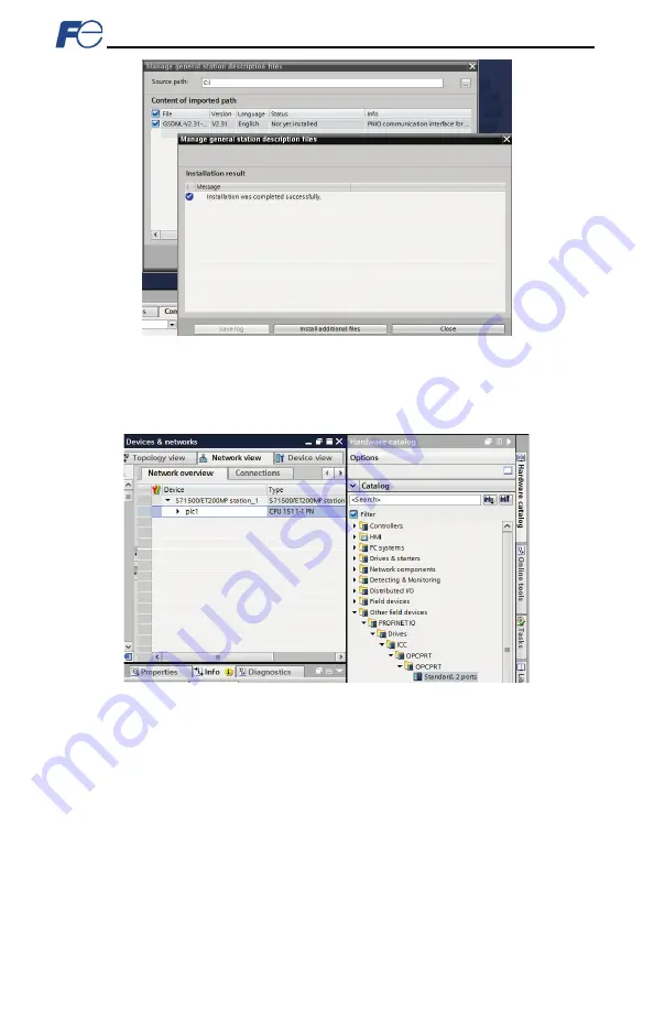
Figure 90: Successfully Installed GSDML File 

This will update the 

Hardware catalog

. Locate the device in the 

Hardware catalog

. In the 

Project tree,


double-click on 

Device & networks.

 Select the 

Network view

 tab and locate the device in the 

Hardware catalog

 as shown in Figure 91. 


Figure 91: Updated Hardware Catalog  


Summary of Contents for OPC-PRT

Page 1: ...orks Please read this instruction manual thoroughly in order to become familiar with the proper interface handling installation and usage procedures Improper handling may inhibit correct operation or...

Page 2: ...EMS Life support devices or systems are devices or systems intended to sustain life and whose failure to perform when properly used in accordance with instructions for use provided in the labeling and...

Page 3: ...ubject to change without notice Please be sure to refer to the most recent available versions Safety precautions Please read this instruction manual thoroughly prior to proceeding with installation co...

Page 4: ...ng during installation or removal may cause equipment failure Do not subject the cables to scratches excessive stress heavy loads or pinching To prevent damage due to electrostatic discharge always to...

Page 5: ...so may cause electrical shock or injuries For clarity purposes illustrations in this manual may be drawn with covers or safety guards removed Ensure all covers and safety guards are properly installed...

Page 6: ...to Network Timeout Conditions 22 4 FUNCTION CODE NUMBERING AND BEHAVIOR 23 4 1 Register Numbers 23 4 2 Scanned Function Codes 26 4 3 Commonly Used Function Codes 26 5 FUJI CONFIGURATION STUDIO 28 5 1...

Page 7: ...52 9 1 4 Connection Timeout Options 53 9 1 5 Node Settings 54 9 1 6 Holding Input Register Remap Settings 54 9 2 EtherNet IP 55 9 2 1 Overview 55 9 2 2 Server Settings 55 9 2 3 Connection Timeout Opt...

Page 8: ...7 9 4 16 Multi state Value Object Settings 97 9 5 PROFINET IO 98 9 5 1 Overview 98 9 5 2 Device Settings 98 9 5 3 Connection Timeout Options 98 9 5 4 Cyclic I O Produced and Consumed Data Access Setti...

Page 9: ...ote that different interface firmware versions may provide varying levels of support for the various protocols When using this manual therefore always keep in mind the release date of the firmware ver...

Page 10: ...s over cables Cable Type CAT5 type 8 conductor UTP patch cables Cable Length 100m per segment max Topologies Star Tree Linear Bus Daisy chain Ring MRP Table 4 Modbus TCP Specifications Item Descriptio...

Page 11: ...Connections 16 Total for both Class 1 and Class 3 RPI Min 1ms I O Input Size Max 32 input words user configurable I O Output Size Max 32 output words user configurable Generic User Configurable Assem...

Page 12: ...Read Size 240 bytes 120 16 bit Integers Max Write Size 240 bytes 120 16 bit Integers Table 7 BACnet IP Specifications Item Description BACnet IP Annex J Protocol Revision 2 Standard Device Profile An...

Page 13: ...DP Yes I M I M0 Alarms Plug Pull Number of Controllers Allows access to only 1 controller Table 9 Applicable Inverters Series Type Capacity ROM version FRENIC Ace FRN E2 All capacities 0300 or higher...

Page 14: ...and that no damage occurred during shipment OPC PRT interface board with spacer and captive M3 x 12mm screw in lower right corner refer to Figure 1 One separate M3 x 6mm mounting screw see Figure 2 T...

Page 15: ...he inverter s control board Refer to section 2 2 Inverter Control Board Connector Attaches to the inverter s connector board which may vary depending on the inverter model USB Port USB 2 0 port with m...

Page 16: ...Activity Status Note Off Device Off The inverter power is off Green Blink Red Blink Startup Startup blink sequence Green On Device On Normal status Green Blink Discovery identification PROFINET discov...

Page 17: ...onnected to the correct terminals and observe all wiring polarity indicators Only one additional option card may be used when the OPC PRT is installed in the inverter If two additional option cards ar...

Page 18: ...17 Figure 5 Installation for 15 kW and Smaller Inverters Interface Card Connector Board Option Case...

Page 19: ...18 Figure 6 Installation for 18 5 kW to 22 kW Inverters Interface Card Connector Board Option Case...

Page 20: ...lure 3 Secure the interface card to the connector board PCB by first tightening the captive M3 x 12mm screw into the inverter standoff located at the lower right hand corner of the interface card Next...

Page 21: ...nverter s input power or motor wires 5 Reinstall all covers removed in step 1 Take a moment to confirm that the Ethernet cables are not being pinched and are not routed near any power carrying wiring...

Page 22: ...etwork or whether the inverter will be locally controlled and therefore only monitored and or configured via the network Bus Link Function Mode Selection y98 If the inverter is to be controlled from t...

Page 23: ...within the time specified by o28 ignore the communications error After the timeout coast to a stop and trip er5 3 13 to 15 Maintain present operation ignoring the communications error no er5 trip 10...

Page 24: ...nction code therefore the group number is first multiplied by 256 then added to the offset number plus 1 This operation is expressed mathematically via Equation 1 1 number offset 256 x number group re...

Page 25: ...1 769 P03 motor 1 rated current 3 x 256 3 1 772 P99 3 x 256 99 1 868 H High Performance Functions 4 H00 4 x 256 0 1 1025 H11 deceleration mode 4 x 256 11 1 1036 H99 4 x 256 99 1 1124 A Motor 2 Parame...

Page 26: ...0 alarm history latest 16 x 256 0 1 4097 X99 16 x 256 99 1 4196 Z Alarm Data 2 17 Z00 17 x 256 0 1 4353 Z53 3 rd last alarm torque 17 x 256 53 1 4406 Z99 17 x 256 99 1 4452 b Motor 3 Parameters 18 b00...

Page 27: ...range the interface card will not generate a corresponding error However if end to end confirmation of such data writes is required then the function code can be read over the network at a later time...

Page 28: ...27 Table 16 Structure of Operation status Function code M14 Table 17 Structure of Rotation Speed Function code W08...

Page 29: ...efer to the relevant protocol section Figure 8 Fuji Configuration Studio Creating a Device Configuration A device can be added to the Project panel for configuration by first selecting the Device Conf...

Page 30: ...tom of the Project panel and dragging and dropping the device in the trash will remove it from the project Hitting the DELETE key on the keyboard when the device is selected in the Project panel Right...

Page 31: ...ensitive menu Hitting the ENTER key on the keyboard when the object is selected Dragging it into the Project panel Selecting it and selecting Add Selected Device from the Edit menu Selecting it and cl...

Page 32: ...em to the desired location If the item is dragged outside of the items in the project tree it will be moved to the end 5 3 Ethernet Settings The Ethernet Settings panel contains Ethernet related items...

Page 33: ...a timeout event is triggered by a protocol the timeout objects are parsed and written to the corresponding function code s The timeout object s will be executed sequentially from first to last To add...

Page 34: ...ubleshooting and add the studio as a program exception to the firewall configuration if necessary It may be necessary to restart your PC before the new firewall configuration can take effect The netwo...

Page 35: ...The parameter values can be backed up from the inverter and restored to the inverter refer to Figure 14 and Figure 15 This allows for easy inverter cloning The backup parameter values are stored as a...

Page 36: ...and configurations Please backup the configuration before executing this feature The factory settings can be restored by Right clicking on the device in the Project panel and choosing Restore Factory...

Page 37: ...the client computer Note that in order to view the interface s web page the free Adobe Flash Player browser plug in is required The plug in can be downloaded from http www adobe com Figure 16 Embedded...

Page 38: ...pplication Functions 2 d function codes are available PID Control 1 J1 function codes are available Link Functions y function codes are available Command Data S function codes are available Monitor Da...

Page 39: ...a word into the filter entry box and then click the filter button Refer to Figure 20 The filter will then display only those function codes currently available in the Function Code List that satisfy...

Page 40: ...a time and each gauge window can be configured to display any scanned function code s value via one of six different gauge types User defined engineering units scaling and range limits are also config...

Page 41: ...nfigured accordingly refer to section 3 1 General purpose input terminal command buttons These buttons labeled X1 through X9 map to the corresponding bits in the inverter s operation command word func...

Page 42: ...the right or left buttons the gauge windows will scroll in the corresponding direction 6 3 4 Gauge Window Configuration Each of the gauge windows can be independently configured to display a user def...

Page 43: ...the bottom of each gauge window The following is a summary of the different available gauge types Gauge Refer to Figure 27 This type of meter implements a rotary dial type display format The indicated...

Page 44: ...ue as well as the maximum negative indicated value Thermometer Refer to Figure 31 This type of meter implements the universally identifiable thermometer display format Hovering the mouse pointer over...

Page 45: ...gure 33 Zooming 6 3 5 Submitting Changes Whenever any of the gauge window configuration items in the Dashboard Tab have been changed the submit button located on the right hand portion of the web page...

Page 46: ...ver content ensure that initial file index htm exists All files accessed by the web server itself must reside in the WEB folder Note that this does not restrict active web server content to using only...

Page 47: ...ds the active content which initiates communication with the server Server Device Content is loaded onto server device s file system for web server 2 Active web content is delivered to client XML sock...

Page 48: ...xadecimal value e g 1F4 for a decimal value of 500 write_data Yes load_file Yes The absolute file path must start with a forward slash store_file Yes reinit No Reinitializes only the configurable driv...

Page 49: ...the interface card s file system in the same manner as though they were traditional files stored on a local or remote PC Note that the USB and FTP connection will prevent the file system from being a...

Page 50: ...ools available such as Windows Command Prompt Core FTP FileZilla SmartFTP etc that can also be used to reliably access the card s file system 7 4 Loading New Web Server Content The interface card s we...

Page 51: ...r 3 Delete the WEB folder from the card s file system 4 Copy the new WEB folder to the card s file system 5 Although it is not typical if your param xml file was specially modified for a custom applic...

Page 52: ...mportant notices behavior precautions or configuration requirements prior to updating your firmware 4 Ensure that the device is in a safe state prior to initiating the firmware update The card may be...

Page 53: ...identifier UI field of the request packets is ignored and is echoed in the response Modbus TCP should not be confused with Modbus serial over TCP Modbus over TCP is not compatible with Modbus TCP and...

Page 54: ...ion is abnormally terminated or lost While this feature provides an additional level of fail safe functionality for those applications that require it there are several ramifications that must be unde...

Page 55: ...were desired to read the inverter s output frequency function code M09 register 2058 operation status function code M14 register 2063 and Life of cooling fan function code M48 register 2097 this coul...

Page 56: ...on the internet Supports DLR Device Level Ring node Supports unconnected messages UCMM and up to 16 simultaneous class 1 I O or class 3 explicit connections Class 1 implicit I O supports both multica...

Page 57: ...the checkbox is checked then the driver will perform the Timeout Action Timeout Action Select an action from the drop down menu None No effect The inverter will continue to operate with the last avail...

Page 58: ...ne 9 2 5 Generic Class 1 I O Connection Access Clients may access the class 1 endpoint by opening a connection to assembly instances 100 and 150 The structure of I O consumed and produced data for thi...

Page 59: ...Mapping Detail Run Fwd forward rotation command 0 forward rotation off 1 forward rotation on Maps to inverter function code S06 bit 0 function code S06 operation command word FWD bit Run Rev reverse r...

Page 60: ...therNet IP specification object library for detailed information on the Control Supervisor Object state machine Speed Actual Inverter operating speed in RPM Maps to function code M09 output frequency...

Page 61: ...f Tag names are generated according to the following structure function code group function code offset Where function code group is a 1 to 2 character field and is the ASCII character s for the funct...

Page 62: ...name we will use EIP and an IP address deselect Open Module Properties and click OK 8 Download the configuration 9 Switch to online mode Right click on the 1756 ENBT A module in the I O Configuration...

Page 63: ...ControlLogix PLC Once an I O connection is established it is automatically synchronized at an interval defined by the Requested Packet Interval RPI 1 Register the interface card s EDS file In the menu...

Page 64: ...ght click on the 1756 ENBT A node under the I O Configuration in the controller organizer view and choose New Module 11 Find the interface card in the Select Module dialog box as shown in Figure 45 Fi...

Page 65: ...see the interface card in the 1756 ENBT A branch under the I O Configuration in the controller organizer view The full I O Configuration tree should appear similar to Figure 48 Figure 48 AOP Interfac...

Page 66: ...project to the PLC Verify that the newly added inverter is available and operating correctly by observing any indications shown on the inverter s icon When the inverter s icon is selected its status a...

Page 67: ...nfirm that the interface card s Network Status LED should be solid green indicating an online connected state 5 By double clicking Controller Tags in the project tree it is possible to view the newly...

Page 68: ...O Configuration in the controller organizer view and choose New Module 3 Choose Generic Ethernet Module in the Select Module dialog box and click Create Refer to Figure 51 Figure 51 Adding a New Gener...

Page 69: ...onsumed data word configuration with two relevant function codes S06 and S05 We therefore set the Output Size to 2 Configuration The Configuration Assembly Instance is unused and its instance number a...

Page 70: ...de S06 which is the inverter s command register A value of 0x0001 therefore means that the FWD run forward bit has been turned ON Similarly we can see that the second 16 bit word of output data Interf...

Page 71: ...uble click MainRoutine under Tasks MainTask MainProgram in the controller organizer view 6 Right click on the first ladder logic rung in the MainRoutine window and select Add Ladder Element 7 The Add...

Page 72: ...he steps in section 9 2 11 Please note that the Assembly Input Instance must be changed to 71 and the Assembly Output Instance must be changed to 21 Refer to Figure 61 Figure 61 AC DC Drive Profile Ge...

Page 73: ...ght click on the first ladder logic rung in the MainRoutine window and select Add Ladder Element 7 The Add Ladder Element window appears 8 Select the AC DC drive profile add on instruction in the Add...

Page 74: ...73 Figure 65 Configure AC DC Drive Profile AOI 11 The program is now complete 12 Save download and run the program...

Page 75: ...est if a connection failure occurs f Collapse the connection tag again by clicking on the sign next to the tag name g Select the Edit Tags tab again Create another new tag by entering data_array in th...

Page 76: ...on The Message Configuration window will open Refer to Figure 70 Figure 70 MSG Instruction Configuration c Configuration tab settings i Change the Message Type to CIP Data Table Read ii In the Source...

Page 77: ...ssion If disabled unchecked the connection is opened before and closed after every transmission For efficiency it is recommended to enable Cache Connections e Click OK to close the MSG Configuration d...

Page 78: ...unction codes being read from the interface card double click Controller Tags in the controller organizer view b Select the Monitor Tags tab and expand the data_array tag c 21 function code values sta...

Page 79: ...be replaced in an actual application program by user provided logic that controls the conditions under which write operations would be performed Figure 75 Reading and Writing via MSG Instructions Fig...

Page 80: ...the limitations of the programming software but is a value of 13668 max Refer to section 4 1 for the function code to register mapping Table 26 provides some examples of various combinations of file s...

Page 81: ...Array Max Number of Accessible Elements N50 0 N50 0 1st 32 N50 N50 15 N50 15 16th 16 N50 N50 31 N50 31 32nd 1 The application PLC program uses a MSG instruction that is configured with a Data Table A...

Page 82: ...ctionality of the MSG instruction which will perform the data read c Follow the same procedure to create a data file This file will be used to store the incoming data read from the interface card Ente...

Page 83: ...figure the MSG instruction a Set the Read Write field to Read Target Device field to PLC5 Local Remote field to Local and Control Block to N20 0 b Upon hitting the ENTER key while in the Control Block...

Page 84: ...et the Channel field to 1 Ethernet d Under Target Device set the Data Table Address field to N30 50 starting target register 2050 and set the MultiHop field to Yes to cause the MultiHop tab to appear...

Page 85: ...ring the MSG instruction at a specific rate or under specific conditions 7 The program is now complete Refer to Figure 84 Figure 84 Completed PLC Program 8 Save download and run the program a To view...

Page 86: ...85 Figure 85 Monitoring the Data Being Read from the Inverter...

Page 87: ...igure 86 shows an example of two MSG instructions one for reading and one for writing It is evident from this logic that N20 and N21 are the two independent message control files created for these ins...

Page 88: ...Specific Controller B ASC BACnet Smart Sensor B SS BACnet Smart Actuator B SA BACnet Interoperability Building Blocks Supported Annex K Data Sharing ReadProperty B DS RP B Data Sharing ReadPropertyMu...

Page 89: ...he gateway supports N A Datatypes Supported The following table summarizes the datatypes that are accepted in the case of a write property service and returned in the case of a read property service w...

Page 90: ...ntation Support R APDU Timeout R Number APDU Retries R Device Address Binding R Database Revision R R readable using BACnet services W readable and writable using BACnet services Table 29 BACnet Binar...

Page 91: ...lt R R R readable using BACnet services W readable and writable using BACnet services Table 31 BACnet Multi state Object Types Properties Supported Property Object Type Multi state Input Multi state O...

Page 92: ...off BI12 ALARM Alarm on off BI13 COMM_ESTABLISHED Communications established on off BI14 BUSY_WRITING Busy writing on off Table 33 Binary Output Object Instance Summary Instance ID Object Name Descrip...

Page 93: ...bit 10 BI12 Indicates alarm Corresponds to function code M14 bit 11 BI13 Indicates communications established Corresponds to function code M14 bit 12 BI14 Indicates function code write in progress Cor...

Page 94: ...net network Enter a string of between 1 and 32 characters in length Instance Number Defines the node s instance number The instance number must be unique across the entire BACnet network Enter a value...

Page 95: ...ay are NULL 9 4 10 Analog Value Object Settings Object Name The name of the BACnet object Enter a string of between 1 and 32 characters in length All object names must be unique within a node Instance...

Page 96: ...field is optional and may be left blank Polarity Indicates the relationship between the physical state of the object as stored in the function code and the logical state represented by the object s pr...

Page 97: ...BACnet object Enter a string of between 1 and 32 characters in length All object names must be unique within a node Instance The BACnet object s instance number Enter a value between 0 4194302 0x0 0x3...

Page 98: ...etween 1 and 32 characters in length All object names must be unique within a node Instance The BACnet object s instance number Enter a value between 0 4194302 0x0 0x3FFFFE Function Code The inverter...

Page 99: ...the PROFINET controller and is at least three times the IO Cycle update time The timeout value is also known as the IO Cycle Watchdog time 9 5 2 Device Settings In the studio s Project panel navigate...

Page 100: ...r function code will populate this word offset of the produced data that is to be sent to the controller It is recommended to start at word offset 0 Consumed Data Word Offset The consumed data receive...

Page 101: ...icance Description 0 STW1 Control word 1 ZSW1 Status word 1 1 NSOLL_A Reference speed setpoint NIST_A Speed actual 9 5 5 2 PROFIdrive Control and Status Words The control word STW1 is the principal me...

Page 102: ...ontrol by PLC is enabled as indicated by RL Refer to function code M14 bit 12 0 No Control Requested Control is not possible by the controller as indicated by RL Refer to function code M14 bit 12 10 1...

Page 103: ...the maximum frequency A positive normalized value indicates forward rotation and a negative normalized value indicates reverse rotation The value of F03 is read by the interface card only at boot up...

Page 104: ...4 1 The length is specified according to the number of bytes to access Since each register corresponds to 2 bytes of data the length must be an even number 9 5 7 TIA Portal STEP 7 Hardware Configurat...

Page 105: ...ll update the Hardware catalog Locate the device in the Hardware catalog In the Project tree double click on Device networks Select the Network view tab and locate the device in the Hardware catalog a...

Page 106: ...will assign the device to the PROFINET IO system as shown in Figure 94 Figure 94 PROFINET IO System 9 5 7 4 Assign IO Module Click on the device and then click on the Device view tab In the Hardware c...

Page 107: ...ode Assign a unique and compatible IP address for this device as shown in Figure 96 Figure 96 Assign Unique Compatible IP Address Assign a unique PROFINET device name as shown in Figure 97 Figure 97 A...

Page 108: ...terface and click the Start search button to discover and display the PROFINET devices on the network as shown in Figure 99 Select the device and click the Apply button Figure 99 Discover PROFINET Dev...

Page 109: ...8 GE Proficy Configuration Example The following example will use GE Proficy Machine Edition SIM11 to demonstrate the basic procedure for configuring a PROFINET device The example will not cover all...

Page 110: ...GSDML file Click the Open button to register the GSDML as shown in Figure 104 It is recommended to use the latest GSDML which is available via the product web page on the internet Figure 104 Register...

Page 111: ...Catalog and click the OK button as shown in Figure 105 The device is added under the Profinet Controller node as shown in Figure 106 Figure 106 Added Device to Configuration 9 5 8 3 Assign IO Module...

Page 112: ...our application Click the OK button as shown in Figure 108 Figure 108 Add IO Module The module will be reflected in the Navigator panel under the device as shown in Figure 109 Figure 109 Added IO Modu...

Page 113: ...and compatible IP Address For this example the IP Address is set to 192 168 17 102 The resulting properties are shown in Figure 111 9 5 8 5 Save the Configuration The device configuration is now comp...

Page 114: ...connected to the local Ethernet network Ensure that the card is programmed with compatible network settings Consult with your network administrator to determine the compatible settings Confirm that th...

Page 115: ...ystem and copy a valid default WEB folder to the card s file system Studio cannot discover the card The studio does not display the card under Online Devices Confirm that the card is running normally...

Page 116: ...47520 Westinghouse Dr Fremont CA 94539 Tel 510 440 1060 Fax 510 440 1063 http www americas fujielectric com...

Reviews: