2-10
4.
Serial
Connector
4.
Serial Connector
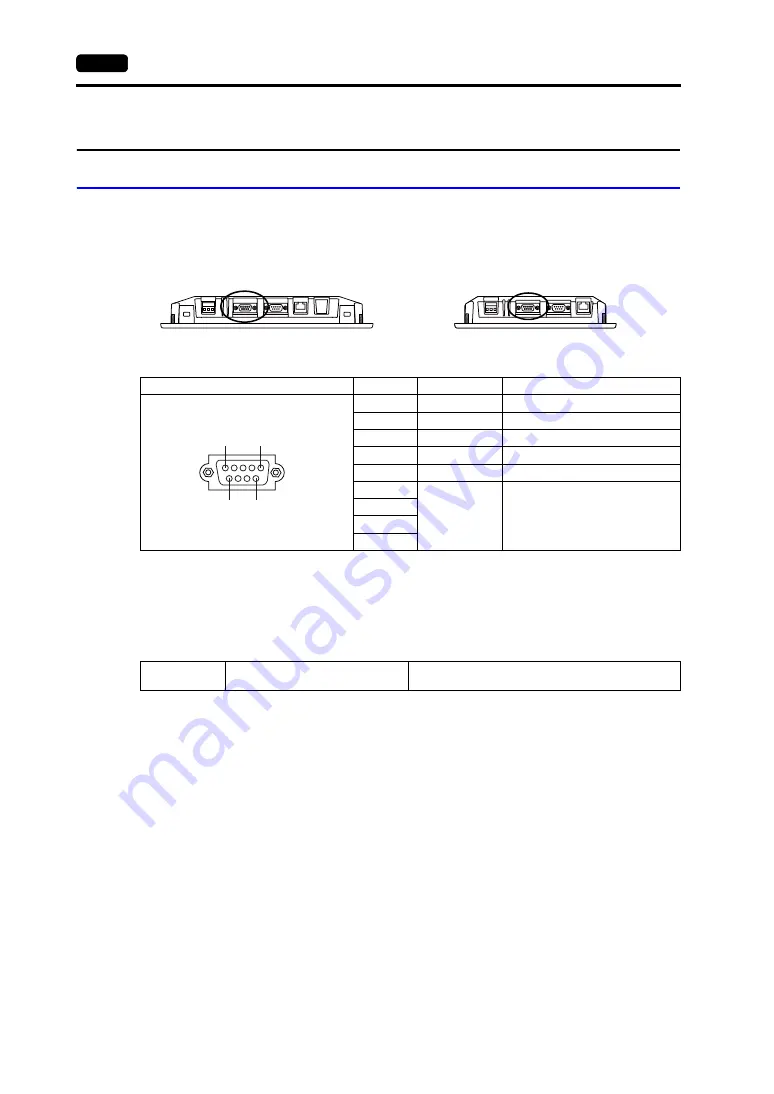
COM1: RS-422/485 Communication Connector
This connector is used to connect a controller via RS-422 (4-wire connection) or RS-485 (2-wire
connection).
The serial connector pins (COM1) correspond to signals as given below.
* Use DIP switches 2 and 3 to switch between RS-422 (4-wire connection) and RS-485 (2-wire connection).
Setting the DIP switches 2 and 3 to ON coRD with +SD, and -RD with -SD in the TS unit.
For more information on DIP switches, refer to page 4-6.
Recommended Connector
The following connector is recommended for a self-made cable.
Connection with PLC/Temperature Controller
The PLC or temperature controller can be connected.
For details on available models or settings on the V-SFT-5, refer to the TS Series Connection Manual.
Bottom view
•
TS1100
Bottom view
•
TS1070
COM1 (D-sub 9-pin, female)
Pin No.
Signal
Contents
1
+RD
Receive data (+)
2
−
RD
Receive data (
−
)
3
−
SD
Send data (
−
)
4
+SD
Send data (+)
5
SG
Signal ground
6
NC
Not used
7
8
9
Recommended
connector
DDK’s 17JE-23090-02(D8C)-CG
D-sub 9-pin / male / inch screw thread (#4-40UNC) type
/ with hood / lead- and cadmium-free
9
5
6
1
Summary of Contents for MONITOUCH TS Series
Page 1: ......
Page 10: ...11 Features 2 Models and Peripheral Equipment 3 System Composition Product Outline ...
Page 43: ...2 26 6 LAN Connector TS1100i TS1070i Only Please use this page freely ...
Page 44: ...31 Mounting Procedure 2 Power Supply Cable Connection Installation ...
Page 49: ...41 Coin type Lithium Battery 2 DIP Switches Handling of TS Series Components ...
Page 57: ...4 8 2 DIP Switches Please use this page freely ...
Page 58: ...51 Before Operation 2 Main Menu Screen 3 System Menu TS Series Operations ...
Page 102: ...5 44 3 System Menu Please use this page freely ...
Page 103: ...61 Error Messages 2 Troubleshooting Error Handling ...
Page 110: ...71 Inspection and Maintenance 2 Warranty Policy Inspection and Maintenance ...
Page 114: ...7 4 2 Warranty Policy Please use this page freely ...


