


5
2. Main Menu Screen
5-31
TS Se
rie
s Op
er
ations
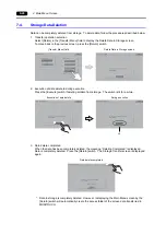
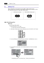
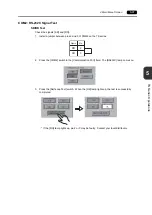
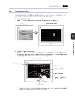
COM2: RS-232C Signal Test
SD/RD Test
Check the signals [SD] and [RD].
1. Install a jumper between pins 2 and 3 of COM2 on the TS series.
2. Press the [COM2] switch in the [Communication Port] field. The [RS232C] lamp comes on.
3. Press the [Self-Loop Test] switch. When the [OK] lamp lights up, the test is successfully
completed.
* If the [NG] lamp lights up, pin 2 or 3 may be faulty. Contact your local distributor.
SD
RD
2
3
Name
No.
Summary of Contents for MONITOUCH TS Series
Page 1: ......
Page 10: ...11 Features 2 Models and Peripheral Equipment 3 System Composition Product Outline ...
Page 43: ...2 26 6 LAN Connector TS1100i TS1070i Only Please use this page freely ...
Page 44: ...31 Mounting Procedure 2 Power Supply Cable Connection Installation ...
Page 49: ...41 Coin type Lithium Battery 2 DIP Switches Handling of TS Series Components ...
Page 57: ...4 8 2 DIP Switches Please use this page freely ...
Page 58: ...51 Before Operation 2 Main Menu Screen 3 System Menu TS Series Operations ...
Page 102: ...5 44 3 System Menu Please use this page freely ...
Page 103: ...61 Error Messages 2 Troubleshooting Error Handling ...
Page 110: ...71 Inspection and Maintenance 2 Warranty Policy Inspection and Maintenance ...
Page 114: ...7 4 2 Warranty Policy Please use this page freely ...