


33
Turn the frontlet so that one of the possible positions with the end of the screw is adjusted in one
line. Then screw on the srews clockwise so that they were guided through the particular holes
and adjust the hinge plates.
4.7 SELECTION OF COLOURING NUMBER The colouring number can be adjusted manually by
hand from 9 to 13. From the colouring table you will see the correct colouring number for the
personally selected application. Select the colouring by turning the knob as long as the arrow
shows the correct colour.
4.8 SELECTION OF DELAY TIME If welding is interrupted the view automatically changes from
dark to light but with a preset delay to dim the glaring light on the working piece from
reannealing. The delay or reaction time can be set as required, either 'fast' (0,25 up to 0,35 s) or
'slow' (0,6 up to 0,8 s) by applying the switch at the back of the cassette (see pict.3).
4.9 SENSITIVITY The sensitivity can be adjusted to ‘high’ or ‘low’ by applying the switch at the
back of the cassette. 'High' adjustment is the normal setting for daily use. If the usage of the
helmet is disturbed by too much light or by another welding device near the working place, the
setting shows ‘low’ (see pict.3).
4.10 Now the helmet is ready to start working. The colouring number can be adjusted during the
application due to turning at the knob.
5. MAINTENANCE
5.1 REPLACEMENT OF THE OUTSIDE SCREEN. Carefully insert finger or thumb into the
recess at the support for the protection screen and carefully fold the support upwards until the
screen comes out at one side. Press out the old protection screen out of the support. Remove
the protection film from the new protection screen and insert it at one side under a terminal strip
at the helmet. Now press onto the other side of the protection screen and let it snap in.
5.2 REPLACEMENT OT AUTOMATIC CASSETTE (see pict. 5a and 5b) Remove the colouring
adjustment knob and turn the nut from the threaded pin which projects sideways out of the
helmet. Let the potentiometer hang loosely at the cable. The cassette is held tightly from a metal
spring like shown in pict. 5b. Loosen the front side of the clamping spring (pict. 5a-D) by pulling
these out of the safety nose (pict. 5a-E) and turn the clamping spring upwards so that it is not
obstructive. Lift up the cassette with the potentiometer hanging at the cable out of the support.
5.3 INSTALLATION OF THE NEW AUTOMATIC CASSETTE Take the new cassette and make
sure that the cable of the potentiometer is under the clamping spring before you put the cassette
into the support inside the helmet. Turn the clamping spring downwards and fix it tightly und the
safety nose like shown in pict.5b.
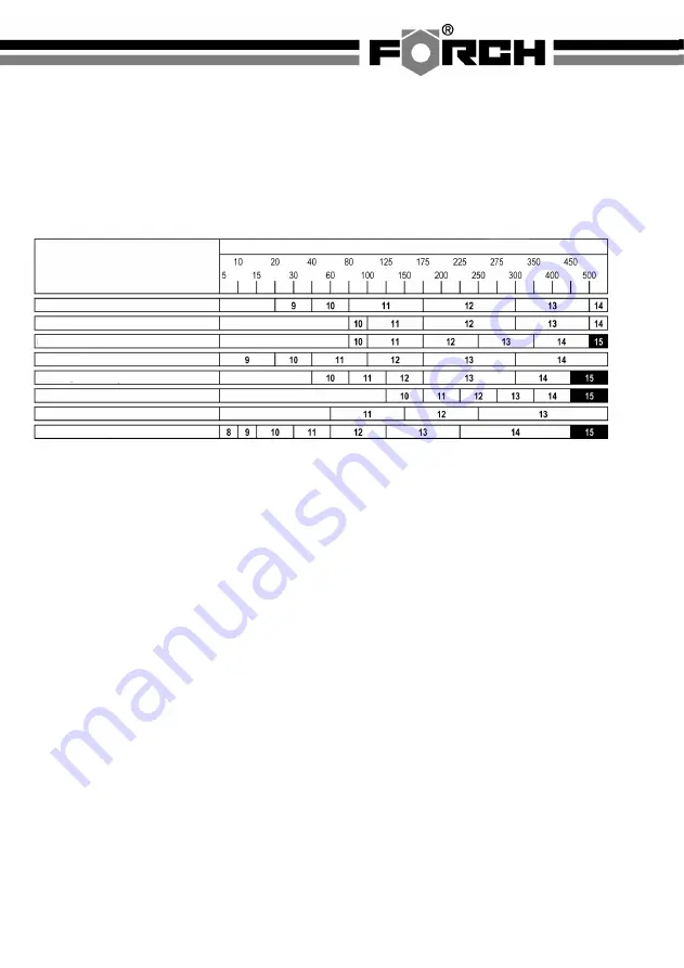
Colouring Table
ARC WELDING CURRENT (AMPERAGE)
Welding process
MIG
for heavy metals
MIG
for easy alloying
WIG,GTAW
Wolfram-Inert gas
MAG/CO2
metal active gas welding
SAW
semi automatic UP welding
PAC
plasma arc welding
PAW
plasma arc welding
SMAW
metal arc welding
Summary of Contents for 5400 400
Page 35: ...35...


