•
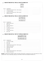
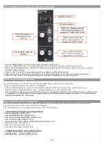
CONNECTIONS DETAIL FOR ACU CON4P CONNECTOR
Pin #
Description
1
CAN bus communication line: CAN-H signal
2
+12V main supply
3
CAN bus communication line: CAN-L signal
4
GND main supply
•
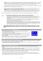
CONNECTIONS DETAIL FOR ACU CON8P CONNECTOR
Pin #
Description
1
GND for Pitch Servo
2
Not used
3
GND for Roll Servo
4
Not used
5
+12V for Pitch Servo
6
Not used
7
+12V for Roll Servo
8
Not used
•
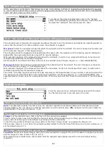
CONNECTIONS DETAIL FOR FX75 SERVO CONNECTOR
Pin #
Description
1
+12V power supply
2
Not used
3
Not used
4
CAN bus communication line: CAN-L signal
5
CAN bus termination
6
GND power supply
7
Not used
8
Not used
9
CAN bus communication line: CAN-H signal
10
CAN bus termination
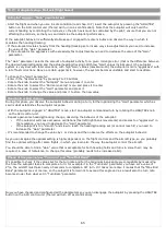
NOTE:
The CAN bus termination (pin#5 connected with pin#10) must be done only on the last servo of the
CAN bus line. If you install only one servo, the CAN line must be terminated on that servo.
57
Summary of Contents for Eclipse
Page 6: ...ECLIPSE PART I INSTALLATION 6 ...
Page 7: ...2 Dimensions 7 ...

