


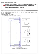


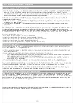


Horizontal installation
(Dimensions are in millimeters, drawing not in scale)
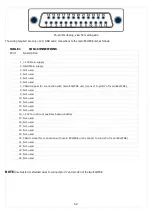
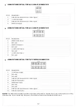
10.3.3 Electrical wirings of the autopilot control unit (Flybox® ACU)
The ACU control unit has two Molex minifit-jr connectors:
- 1 four-pole connector (here called “CON4P”)
- 1 eight-pole connector (here called “CON8P”).
Included in the kit there are the corresponding socket connectors (Molex P/N: 5556-04R for 4-poles connector and
5556-08R for 8-poles connector) and the crimp terminals (Molex P/N: 5556-TL).
Each servos is provided with a 10-poles Molex Microfit connector (Molex 43025-1000) and the corresponding crimp
terminals (Molex 43030-0007).
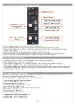
The electrical installation consists of the following wirings:
- 12 Volt power supply: the power supply input is in the ACU control unit and power also the connected servos. Use
wire with adequate sizing to minimize voltage drop and avoid that the wire become warm (recommended size:
AWG18).
Power must be supplied through a breaker connected exclusively to the ACU control unit, easily accessible
to the pilot and clearly identified as “Autopilot”
. If you have one servo only use a 4 Ampere breaker, if you have
two servos use a 7.5 Ampere breaker.
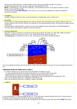
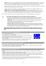
- Wirings between ACU control unit and ECLIPSE: the ACU is connected to the Eclipse with a two-wires CAN bus
communication line. Use a two-pole twisted cable or a two-pole with shield cable (shield connected to ground in one
point only). AWG24 wires should be enough.
- Wirings of the servos: each servo need to be connected to the ACU control unit with two wires for the power supply
(use AWG18 wires) and need to be connected to the CAN bus communication line using a two-pole twisted cable or a
two-pole with shield cable (shield connected to ground in one point only). AWG24 wires should be enough.
NOTE:
Do not route this line in parallel with transmitting antennas or other sources of known RF interference.
Do not route this line in parallel with microphone cables or audio cables to avoid audible noise in headphones.
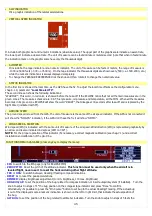
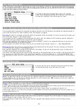
- Wiring of the remote disengage button (RECOMMENDED): connect it between ground and pin#6 of CON3 Eclipse
connector.
NOTES:
- Care should be taken to avoid that the wiring is subjected to chafing or excessive flexing.
- Avoid if possible junctions, that with excessive vibration may be subjected to fail or short-circuit.
56
Summary of Contents for Eclipse
Page 6: ...ECLIPSE PART I INSTALLATION 6 ...
Page 7: ...2 Dimensions 7 ...