


Fuel level sensors
- ECLIPSE has 3 fuel level inputs that can be connected to both resistive sensors (with max resistance of 300 ohm) and
capacitive sensors (with output voltage from 0~5 Volt).
- Resistive sensors can be of two types, both supported by ECLIPSE: resistive sensors that increase resistance as you
add fuel and resistive sensors that decrease resistance as you add fuel.
- It's also possible to install a mixed type of sensors (i.e. 2 res 2 capacitive).
- All fuel level sensors connected to ECLIPSE must not be connected to any other instrument. Disconnect any
previously used instrument.
•
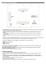
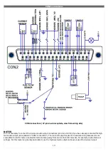
FUEL LEVEL SENSORS CONNECTION:
Refer to fuel level sensors manual for the
detailed electrical and mechanical
installation.
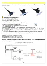
- Make sure that the fuel level sensors are mounted so that all the fuel in the tank can be measured. If the fuel sensor
cannot measure completely the fuel in the tank the ECLIPSE will display inaccurate readings.
For example (pic.1) if a fuel sensor cannot measure the lowest part of the tank that contains 7 liters, ECLIPSE will display “0”
(zero) for fuel level of 7 liters and below.
Another example (pic.2) is if a tank can holds 40 liters of fuel but at 25 liters the fuel is at the top of the sensor, the
maximum that ECLIPSE will display is 25 liters.
PIC.1 PIC.2
Fuel pressure sensor
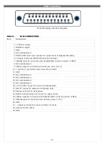
The fuel pressure trafitting is supplied by Flybox®; the electrical connections are:
- white wire (signal out) to pin #5 of CON2 connector
- green wire (GND) to pin #23 of CON2 connector
- brown wire (+12V Supply) to pin #4 of CON2 connector
The pressure range accepted is from 0 to 4 bar.
NOTE:
an improper wiring can cause damage to the fuel pressure transducer.
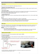
MECHANICAL INSTALLATION HINTS:
- Screw tight the transducer to the fitting; no other seal material is required because the sealing is ensured by the
green fuel-
resistant gasket of the transducer.
- To check that no screw out occur you must mark with a permanent pencil the transducer and fitting:
19
Not measurable
Not measurable
Summary of Contents for Eclipse
Page 6: ...ECLIPSE PART I INSTALLATION 6 ...
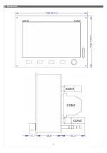
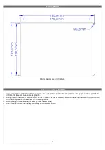
Page 7: ...2 Dimensions 7 ...


