35
To choose a sensor:
1. Select a slot, 1, 2, 3 or 4. Any sensors that are connected will automatically populate this list.
2. Select the desired sensor and exit the function.
To set the alarm limits for a sensor:
1. Activate the function. Make sure that the
icon is displayed in the bottom left corner. If not, press the
icon to enable.
2. Select
[Low alarm]
or
[High alarm]
and then move the wheel to adjust the value.
3. Select the
icon to return to the previous menu.
9.8 Choose Sensors
The main screen can display the value of up to 4 sensors. This function is used to select which sensors to
display.
9.9 Set ASL Pressure
The set ASL
(Above Sea Level)
function is used to calibrate an altitude sensor. When an altitude sensor is
connected, change the
[Air pressure]
setting until the altitude is at 0m.
•
Make sure that your model is at ground level during this process.
When using i-BUS it is possible to drastically reduce the amount of wires within a model.This is possible
because i-BUS enables communication of up to 15 channels through asingle wire without sacrificing resolution
or reaction time.
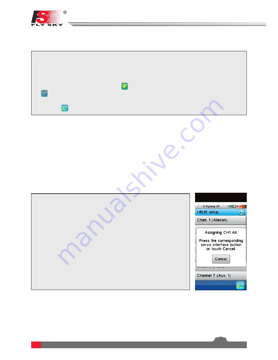
9.10 i-BUS Setup
(Pic.51)
Setup:
1. Connect the i-BUS receiver to the i-BUS output on the RX and connect the
i-BUS receiver to your servos. Chain as many receivers as are needed for
the model setup
(Max 16 Channels)
.
2. Open the RX setup function, navigate to the i-BUS setup utility and select
the desiredchannel to set up. The following message will be displayed
“Press the corresponding servo interface button or touch Cancel”
(If
the wrong selection was made select the cancel option and reselect)
.
3. To complete the channel assignment, press the corresponding button on
the i-BUS receiver
(These buttons are recessed so a small tool is needed
to press the buttons)
. If the channel is successfully assigned the TX will
display the channel name followed by interface number
(If you have
several receivers in series they will be numbered, number 1 being closest
to your RX module)
and the servo number.
4. Repeat this step for each servo in the model setup.
Pic.51
•
There are 2 types of sensors, basic and advanced. A basic sensor only reports back 1 value, but an
advanced sensor is able to monitor several things at once, for example altitude, temperature, pressure.
This function set the refresh rate of the servos connected to the receiver. If the frequency is improperly set, the
servos can malfunction. Please consult the servos user manual for more information.
•
The frequency value is stored in the receiver memory so the receiver must be turned on and connected
during setup.
9.11 Servos Frequency


