68
Flowserve US Inc.
SIHI
dry
dry
dry
dry
Standard
Standard
Standard
Standard M Series
Dry Running Vacuum Pump
Issue Date: November 21, 2016 Copyright:
FLOWSERVE SIHI Pumps Rev 1
10.5.1.3 Removal of the Pump Chamber [Housing]
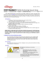
Caution! Handling of heavy parts
Therefore:
For the exchange of the complete SIHIdry
Pump Chamber load of at least 110lb [49.6 kg]!
It is necessary to disassemble the spindle pump housing in order to clean the feeding room or the
displacers, or to replace the pair of spindles.
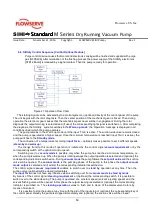
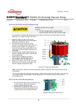
1. Detach the pipe union (B) in the cooling
water line at the position marked in the figure
above the flow indication device.
2. The spindle pump casing is secured by
means of 12 hexagon head screws (90.11) to
the motor casing (10.40). The screws are
located in the upper flange plate of the motor
casing and must be unscrewed and removed
downwards.
3. Screw two lifting shackles M10x60 tightly into
two free opposed tapped holes in the top face
of the pump casing.
4. Carefully lift the spindle pump casing
(10.30), approx. 100lb [45 kg], from the
motor casing (10.40). Using a crane.
5. Remove the dowel pins (56.20) from the
bottom side of the casing. If necessary, they
must be replaced during reassembly.
Figure 27: Pulling of pump chamber
Note: Lift vertically, otherwise the casing might jam against the spindles and both components might
be damaged.
The screw spindle pump casing contains approx. 2.5GAL [9 l] cooling liquid. Should you intend to open
the cooling chamber (as described in the paragraph 10.5.1.5), the pump casing must be put on a
horizontal surface!
10.5.1.4 Removal of the Discharge Branch
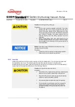
1. Remove the discharge branch (15.60) from the
motor casing (10.40) by loosening the 4
hexagon screws M12x25 (90.13).
2. Remove the ‘O’-ring (41.23) which is in the
flange surface of the discharge branch and
replace by a new one during re-assembly.
Figure 28: Removal of suction cover
Summary of Contents for SIHI dry Standard H Series
Page 82: ......

