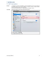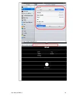
User Manual X8400 sc
37
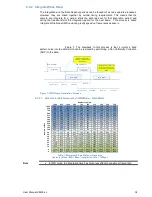
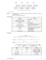
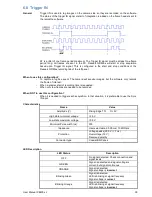
Figure 9: Frame Synchronization - IWR mode
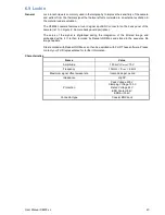
6.7.1 Sync In
General
The Sync IN signal is connected to the camera on connector #4 on Figure 2. The minimum
pulse width is 300 ns.
The Sync IN setup is described in §4.4.7
Characteristics
Name
Value
Amplitude (V)
Rising Edge TTL 0/+5 V
High state minimum voltage
>3.5 V
Low state maximum voltage
<0.5 V
Polarity
User Selectable
Max frequency (Hz)
Maximum Frame Rate of the camera for
a given detector configuration*
Minimum Pulse width (ns)
300
Impedance
User selectable. 50 Ohms / 10 MOhms
Protection
Voltage peaks (500 V / < 1 ns)
Overvoltage (15 V)
Reversed polarity
Connector type
Coaxial BNC Jack
Chronogram
Name
Value
Notes
Jitter
12.5 ns
1 pixel clock (80 MHz)
Fixed Delay
690 ns
Propagation through back
panel card + propagation
from FPGA to detector
Manual Delay
-
Set by user
Integration Time
-
Set by user

