[
5.5.4 — Setup menu
]
© FLIR Systems AB –
Publ. No.
557 369 –
Ed. A
35
5.5.4
Setup menu
This menu contains all the functions for changing the camera setup parameters.
The camera is equipped with a non-volatile memory area that holds all setup
parameters while the camera is switched off. The active measurement function
(e.g.
Spot 1
) and working/inspection directory are also stored in the non-volatile
memory. When the camera is switched on, it retains the same settings as those
before it was last switched off.
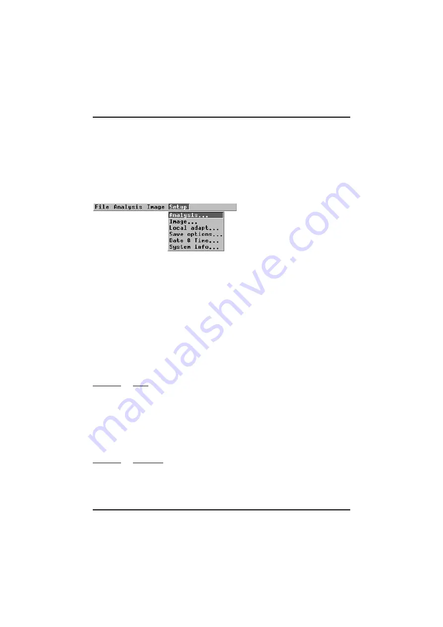
Figure 5.20
Setup
menu.
5.5.4.1
Analysis...
The analysis setup defines the parameters used for the measurement functions
(see “Analysis menu” on page 30). By pressing
↵
when
Analysis
... is highlighted in
the
Setup
menu, the
Analysis
dialog box is displayed on the screen. By moving the
joystick up/down the different dialog box items are selected i.e.
Spot, Area type,
Area function, Profile, Isotherm type, Isotherm width, Isotherm colour, Difference
temp
and
Multiple spots.
By moving the joystick left/right the item parameters will
be changed. When the
↵
button is pressed the parameters are stored and the dia-
log box is removed. If the clear button is pressed the dialog box is removed with-
out storing any changed parameters.
5.5.4.1.1
Spot
There are three modes for the spotmeter function:
Manual
,
Maximum
,
Minimum
. If
Manual
is selected, the spot meter crosshair can be moved with the joystick to the
desired position within the measurement area after having been confirmed in the
Analysis
menu. If
Maximum
or
Minimum
is selected, the spot meter crosshair
automatically moves to the point where it hits the highest or lowest temperature
within the measurement area.
5.5.4.1.2
Area type
The different area types are
Box
and
Circle
. Choosing either of these creates a
box measuring area or a circle measuring area when
Area
is chosen in the
Analy-
sis
menu
Summary of Contents for ThermaCAM PM575
Page 1: ...ThermaCAM PM575 595 Operator s Manual ...
Page 3: ...ThermaCAM PM575 595 FLIR Systems AB May 1999 Publ No 557 369 Ed A Operator s Manual ...
Page 4: ......
Page 16: ... 3 2 Connections ThermaCAM PM575 595 Operator s Manual 8 Figure 3 2 Camera connectors ...
Page 67: ......
Page 68: ......


