6
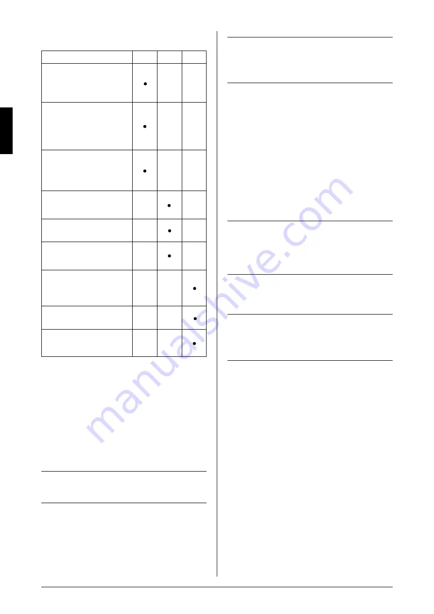
Preventive compressor maintenance
Weekly
Monthly Annually
Check oil level. During standstill
the correct level is between the
maximum and the minimum
indications. Use only genuine SJ-27
synthetic oil. Do not overfill (fig. 5).
Drain condensate from air receiver
(at a pressure of max. 2 bar/30
psi) (fig. 6). If fitted with auto drain,
this will take place automatically,
however, drain bottle has to be
emptied.
If compressor is fitted with outlet
filter, check and empty for water by
pressing the black button. If fitted
with auto drain, this will take place
automatically.
Check compressor, air tubes and
equipment for leaks, and check the
pumping time.
Inspect and replace intake filter, if
necessary.
Clean the compressor with a soft,
damp cloth. Dust and dirt prevent
cooling.
Check the O-ring in the non-return
valve and replace if necessary (fig. 10)
Note! Empty receiver of air before
dismounting.
Check filter and filter elements for
optimum efficiency.
Test the safety valve by gently
pulling the ring with pressure in the
receiver (fig. 7).
Oil change
In connection with repair of model 6 motors, e.g. change
of valve plate or other internal motor parts or in case the
compressor is installed in a very dusty environment, oil change
may be necessary. Proceed as follows:
1. Remove the ribbed cover by loosening the 4 screws (fig. 8).
2. Tilt the motor towards side with outlet and at the same time
hold the internal motor parts in place with hand. Pour all oil
out of housing (fig. 8). In case of dirt particles at the bottom
of the motor housing, clean with a rag.
Note!
Waste oil is to be handled according to the
environmental rules in force in the country.
3. Tilt the motor back and fill with SJ-27 oil (approx. 0.75l) (fig. 8).
4. Clean the edge of casing and cover. Check the O-ring of the
ribbed cover.
5. Replace the ribbed cover and check during operation that
the O-ring is placed correctly to ensure a 100% tight closing
between housing and cover.
Important!
Always use SJ-27 oil as other types of oil may cause
serious mechanical damage to the compressor.
Consequently, the warranty only applies if SJ-27 oil is
used.
Check the pumping time
The pumping time indicates the condition of the compressor
provided that there
are no leaks in the system where the compressed air may leak.
Test the compressor as follows:
1. Empty the air receiver of compressed air (the pressure
gauge shows 0 bar).
2. Close the outlet on the air receiver and check that the drain
cock is closed.
3. Start the compressor and note how long it takes until it
switches off.
Make sure that the pressure in the air receiver is 8 bar/120
psi as deviations may indicate the wrong results (see
technical details).
Important!
Always test the compressor when cold as the time
indicated refers to the pumping time of a cold
compressor. The pumping time of a warm compressor
is much longer and consequently, the result would be
misleading.
Fault finding and repair
Important!
Switch off and isolate from electrical supply before
removing any parts from the compressor.
Empty air receiver of air before dismantling any parts
of compressor unit’s pressure system.
1. Compressor does not start:
a) No power from mains. Check fuses and plug.
b) Breakage or loose joints in electrical connections.
c) The starting relay is defective. Contact your JUN-AIR
distributor.
d) The pressure switch is defective and does not switch on
the compressor.
e) The thermal protection has switched off the compressor
due to overheating. When cooled the compressor will
automatically turn on at a suitable operation tempera-
ture. Go through the points in section 4.
f) Pressure in the air receiver is too high for activation
of the pressure switch. The pressure switch makes
circuit only when pressure has dropped to preset
start pressure. Empty the receiver.
g) The compressor has not been unloaded and there is
back pressure on the piston. Dismount and check
unloader valve (fig. 9). The back pressure may be
due to a leaking non-return valve causing the
compressed air in the receiver to leak back into the
compressor motor. Dismount the non-return valve and
clean or change O-ring (fig. 10).
h) Capacitor defective.
Operating manual
GB
Summary of Contents for JUN-AIR 12 - 15
Page 2: ......
Page 4: ......
Page 33: ...33 Motor spare parts model 3 Motor spare parts model 3 0013001 0013101 Drawings Drawings...
Page 34: ...34 Motor spare parts model 6 Motor spare parts model 6 0015100 0015200 Drawings...
Page 35: ...35 Spare parts model 6 15 0015400 Spare parts model 3 4 6 4 0015300 Drawings...
Page 36: ...36 Spare parts model 6 25 0015450 Spare parts model 12 25 0019700 Drawings...
Page 37: ...37 Spare parts model 18 40 0200660 Spare parts model 12 40 0200650 Drawings...
Page 38: ...38 Spare parts model 24 40 0200670 Spare parts model 36 150 0016500 Drawings...
Page 39: ...39 Accessories 0991041 0015900 0991040 Drawings...
Page 40: ...40 Electrical drawing model 3 6070010 Drawings...
Page 41: ...41 Electrical drawing model 6 6070160 Drawings...
Page 42: ...42 Electrical drawing model 12 6070210 Drawings...
Page 43: ...43 Electrical drawing model 18 6070260 Drawings...
Page 44: ...44 Electrical drawing model 24 400V 50Hz 6070310 Drawings...
Page 45: ...45 Electrical drawing model 24 230V 50 60Hz 6070311 Drawings...
Page 46: ...46 Electrical drawing model 36 400V 50Hz 6070360 Drawings...
Page 47: ...47 Electrical drawing model 36 230V 50Hz 6070361 Drawings...
Page 48: ......
Page 50: ......
Page 51: ......


