Fischer Panda 4000s PMS FC, Manual
The Fischer Panda 4000s PMS FC is a reliable and efficient generator that provides power for your home or RV. For easy maintenance and troubleshooting, be sure to download the free user manual from manualshive.com. This manual includes step-by-step instructions to help you get the most out of your generator.
Share
Download


Reviews:
No comments
Related manuals for 4000s PMS FC
PARTYBOX 200
Brand: JBL Pages: 16

RAINBOW1000
Brand: Ibiza sound Pages: 28

GV 7003A
Brand: Wacker Neuson Pages: 52

PEAQ PPA55BT-BL
Brand: Imtron Pages: 120

73531i
Brand: Champion Pages: 34

BM10722 Series
Brand: Black Max Pages: 40

DE50F4-XX/1
Brand: Winco Pages: 32
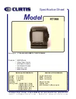
RT068
Brand: Curtis Pages: 1

Sync E
Brand: Tentacle Pages: 14

Spaced360
Brand: Orbitsound Pages: 9

LSA 50.1
Brand: Leroy-Somer Pages: 20

TAL A44
Brand: Leroy-Somer Pages: 28

DS13000E
Brand: DuroStar Pages: 66

EM6000GP
Brand: Honda Pages: 55

WAE BTP03 Mini
Brand: Hercules Pages: 2

SDU-2000e
Brand: Symmetricom Pages: 354

GEN7500DF
Brand: Power Pro Pages: 33

VX-410 Series
Brand: Vertex Standard Pages: 2


