


Firepower MST 140i
Manual 0-5338
4-9
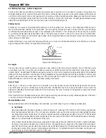
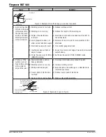
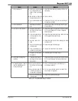
BASIC WELDING GUIDE
FAULT
CAUSE
REMEDY
7 Cold weld puddle
A Welding voltage too high
A Decrease voltage or increase the wirespeed
control.
B Loose welding cable connec-
tion
B Check all welding cable connections.
C Low primary voltage
C Contact supply authority.
D Fault in power source
D Have an Accredited Firepower Service Provider
to test then replace the faulty component.
8 Arc does not have a
crisp sound that short
arc exhibits when the
wirefeed speed and
voltage are adjusted
correctly.
The MIG Gun has been con-
nected to the wrong voltage
polarity on the front panel
Connect the MIG Gun to the positive (+)
welding terminal for solid wires and gas
shielded flux cored wires. Refer to the
electrode wire manufacturer for the correct
polarity.
9 Poor weld result from
setup chart param-
eters
A Incorrect welder setup, polar-
ity, shielding gas, wire type and
size
A Check to make sure that the welder is set up
correctly; also check polarity, shielding gas,
wire type and size.
B Contact tip has arc marks in the
bore causing excessive drag on
the wire
B Replace the contact tip with only a genuine
MST contact tip.
Table 4-4: MIG Welding Problems
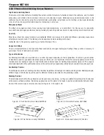
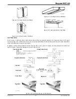
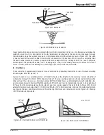
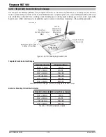
4.03 Stick (SMAW) Basic Welding Technique
Size of Electrode
The electrode size is determined by the thickness of metals being joined and can also be governed by the type of welding
machine available. Small welding machines will only provide sufficient current (amperage) to run the smaller size electrodes.
For thin sections, it is necessary to use smaller electrodes otherwise the arc may burn holes through the job. A little practice
will soon establish the most suitable electrode for a given application.
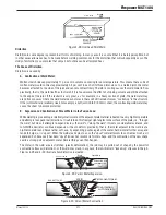
Storage of Electrodes
Always store electrodes in a dry place and in their original containers.
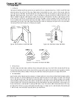
Electrode Polarity
Electrodes are generally connected to the ELECTRODE HOLDER with the Electrode Holder connected positive polarity. The
WORK LEAD is connected negative polarity and is connected to the work piece. If in doubt consult the electrode data sheet
or your nearest Accredited Firepower Distributor.
Summary of Contents for MST 140i
Page 6: ...This Page Intentionally Blank ...
Page 76: ...Firepower MST 140i BASIC WELDING GUIDE 4 24 Manual 0 5338 This Page Intentionally Blank ...
Page 82: ...Firepower MST 140i KEY SPARE PARTS 6 2 Manual 0 5338 6 02 Power Source Art A 12518 31 ...
Page 86: ...Firepower MST 140i KEY SPARE PARTS 6 6 Manual 0 5338 This Page Intentionally Blank ...
Page 87: ...Firepower MST 140i Manual 0 5338 1 APPENDIX APPENDIX This Page Intentionally Blank ...
Page 89: ...Firepower MST 140i Manual 0 5338 3 APPENDIX Art A 12517 ...


