


Firepower MST 140i
INSTALLATION, OPERATION AND SETUP
3-8
Manual 0-5338
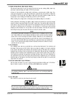
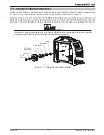
1. Power Indicator
The power indicator is illuminated when the Electricity Supply is applied to the Power Source
System and when the ON/OFF switch located on the rear panel is in the ON position.
POWER
FAULT
1
Art #
A-12???
A
V
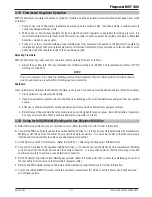
2. Digital Wirespeed/Amperage Meter (Left Digital Display)
This digital meter displays preview Wirespeed in MIG mode only then actual amperage (weld
current) once an arc has been established. It also displays preview amperage in both the
STICK and LIFT TIG modes only then actual amperage (weld current) once an arc has been
established.
At times of non-welding, the amperage meter will display a preview value in both STICK
and LIFT TIG modes. This value can be adjusted by varying the Wire speed / Amperage
potentiometer (Control No. 3). At times of non-welding, the amperage meter will preview a
wirefeed speed value (Inches Per Minute) in MIG mode only. This can be identified as preview
wirefeed speed by a decimal point at the lower right hand side of the display.
When welding, the amperage meter will display actual amperage (weld current) in all modes.
At the completion of welding, the amperage meter will hold the last recorded amperage value
for a period of approximately 10 seconds in all modes. The amperage meter will hold the
value until; (1) any of the front panel controls are adjusted in which case the Power Source
will revert to preview mode, (2) welding is recommenced, in which case actual welding
amperage will be displayed, or (3) a period of 10 seconds elapses following the completion
of welding in which case the Power Source will return to preview mode.
NOTE
The preview functionality provided on this power source is intended to act as a guide
only. Some differences may be observed between preview values and actual welding
values due to factors including the mode of welding, differences in consumables/gas
mixtures, individual welding techniques and the transfer mode of the welding arc (ie
dip versus spray transfer). Where exact settings are required (in the case of procedural
work), it is recommended that alternate measurement methods be utilized to ensure
output values are accurate.
POWER
2
2
2
A
V
2
2
4
4
7
3
3
6
8
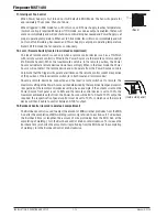
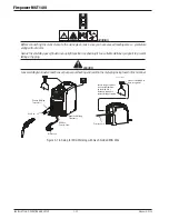
3. Wirespeed/Amperage Control
In MIG mode, the Wirespeed/Amperage control knob adjusts the speed of the wire feed motor
(which in turn adjusts the output current by varying the amount of MIG wire delivered to
the welding arc). The optimum wire speed depends upon the material type and the welding
application. The setup chart on the inside of the wire feed compartment door provides a
brief summary of the required settings for a basic range of MIG (GMAW/FCAW) welding
applications.
In STICK and LIFT TIG modes, the Wirespeed/Amperage control knob adjusts the amount of
amperage (weld current) delivered to the welding arc by the Power Source. It directly adjusts
the Power Source System to deliver the desired level of weld current.
WIRESPEED
DOWNSLOPE (S
10
2
2
9
1
1
ARC FORCE (%
3
WIRESPEED
DOWNSLOPE
ARC FORCE (%
A
V
10
2
2
4
4
7
9
1
1
3
3
6
8
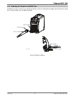
4. MIG Gun
The MIG Gun adapter is euro connection for the Firepower MIG Gun. MIG Gun remote
control is routed through the euro adapter fitting. Connect the MIG Gun by pushing the MIG
Gun connector into the brass MIG Gun Adapter firmly and screw the locking screw in the
MIG Gun Adapter within the Wire Feed Compartment to secure the Firepower MIG Gun in
position. Failure to properly lock the Firepower MIG Gun into the MIG Gun Feedplate will
result in the MIG Gun being pushed out of the MIG Gun Feedplate by the MIG welding wire
or lack of shielding gas (porosity in the weld) at the weld zone.
4
Summary of Contents for MST 140i
Page 6: ...This Page Intentionally Blank ...
Page 76: ...Firepower MST 140i BASIC WELDING GUIDE 4 24 Manual 0 5338 This Page Intentionally Blank ...
Page 82: ...Firepower MST 140i KEY SPARE PARTS 6 2 Manual 0 5338 6 02 Power Source Art A 12518 31 ...
Page 86: ...Firepower MST 140i KEY SPARE PARTS 6 6 Manual 0 5338 This Page Intentionally Blank ...
Page 87: ...Firepower MST 140i Manual 0 5338 1 APPENDIX APPENDIX This Page Intentionally Blank ...
Page 89: ...Firepower MST 140i Manual 0 5338 3 APPENDIX Art A 12517 ...


