Firepower MST 140i
INSTALLATION, OPERATION AND SETUP
3-12
Manual 0-5338
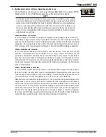
10. Arc Control (Inductance)
The arc control operates in MIG mode only and is used to adjust the intensity of the welding
arc. Lower arc control settings make the arc softer with less weld spatter. Higher arc control
settings give a stronger driving arc which can increase weld penetration. Soft means maximum
inductance while Hard means minimum inductance.
MIG
STICK
4T
2T
SOFT
HARD
2
6
8
10
11
12
MIG
LIFT TIG
STICK
4T
2T
-
HARD
+
SOFT
2
4
6
8
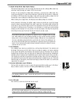
11. Trigger Mode Control (MIG and LIFT TIG Mode only)
The trigger mode control is used to switch the functionality of the of the MIG or TIG Trigger
Switch between 2T (normal) and 4T (latch mode)
2T (Normal Mode)
In this mode, the MIG or TIG Trigger Switch must remain depressed for the welding output
to be active. Press and hold the MIG or TIG Trigger Switch to activate the Power Source
System (weld). Release the MIG or TIG Trigger Switch to cease welding.
4T (Latch Mode)
This mode of welding is mainly used for long welding runs to reduce operator fatigue. In this
mode the operator can press and release the MIG or TIG Trigger Switch and the output will
remain active. To deactivate the Power Source, the trigger switch must again be depressed
and released, thus eliminating the need for the operator to hold the MIG or TIG Trigger Switch
Note that when operating in LIFT TIG mode, the Power Source will remain activated until the
selected Downslope time has elapsed (refer Control No. 9).
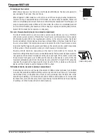
12. Process Selection Control
The process selection control is used to select the desired welding mode. Three modes are
available, MIG, LIFT TIG and STICK modes. Refer to section 3.20 for MIG (GMAW/FCAW)
set up details, section 3.21 for LIFT TIG (GTAW) set-up details or section 3.22 for STICK
(SMAW) set-up details.
Note that when the Power Source is powered off the mode selection control will automatically
default to MIG mode. This is necessary so as to prevent inadvertent arcing should an electrode
holder be connected to the Power Source and mistakenly be in contact with the work piece
during power up.
Summary of Contents for MST 140i
Page 6: ...This Page Intentionally Blank ...
Page 76: ...Firepower MST 140i BASIC WELDING GUIDE 4 24 Manual 0 5338 This Page Intentionally Blank ...
Page 82: ...Firepower MST 140i KEY SPARE PARTS 6 2 Manual 0 5338 6 02 Power Source Art A 12518 31 ...
Page 86: ...Firepower MST 140i KEY SPARE PARTS 6 6 Manual 0 5338 This Page Intentionally Blank ...
Page 87: ...Firepower MST 140i Manual 0 5338 1 APPENDIX APPENDIX This Page Intentionally Blank ...
Page 89: ...Firepower MST 140i Manual 0 5338 3 APPENDIX Art A 12517 ...


