FibroLAN S.CON1M/MA User And Installation Manual Download Page 21

S.CON1M/MA System 


21

 
14 - Troubleshooting 

Prior to performing the following procedures, reset the S.CON1M/MA, set all FP DIP 
switches to TEST mode (disable FP), disable SLE and disable FP for the remote device. 
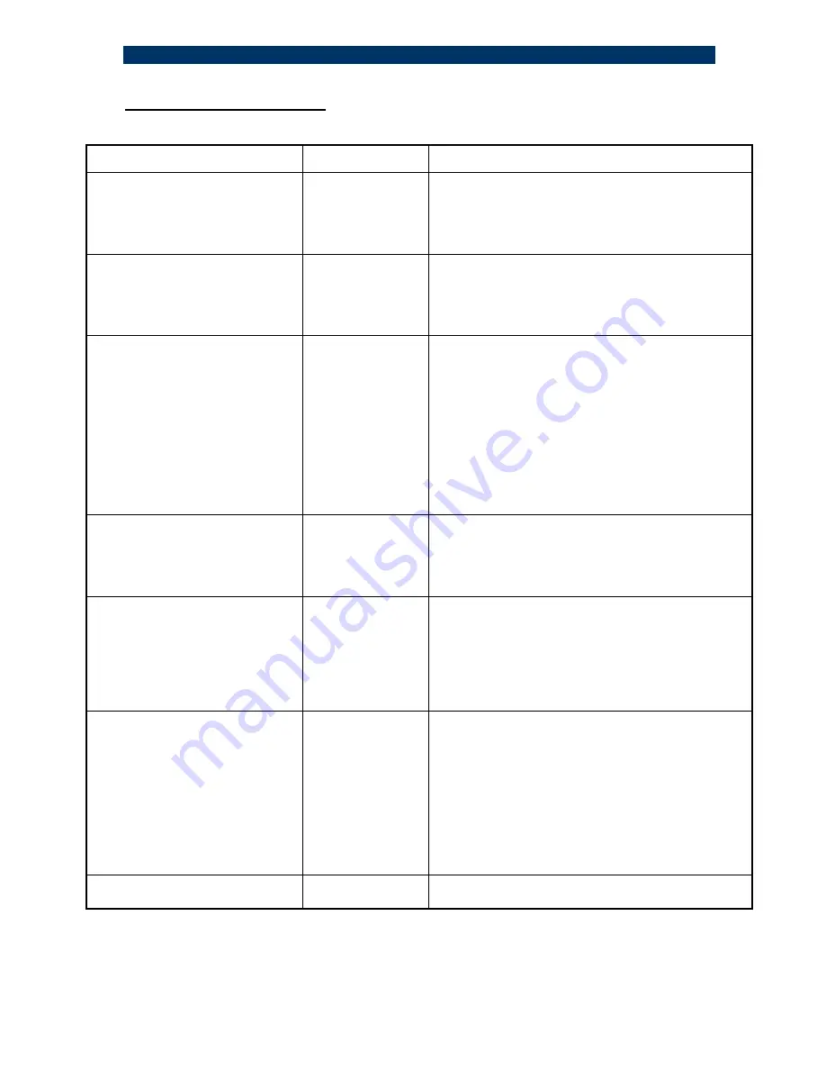
Problem & symptom 

Indication 

Corrective Action 

No power  

Main power

 PWR 

LED not lit 


Check that the power supply cable is firmly 
connected to the main power supply and rack 
mount power source. 
Check that the AC input power source is between 
100 and 240VAC. 

Network problems 

No communication 
on network  

On the “ mode setup “ dip switches, verify that the 
S6 is in the up position (normal position) 
Move S6 to the DOWN position and move it back 
to the UP position after one second (Reset 
operation) 

Copper link not working at all 

Link

 LED not lit 

 Verify if the remote connected TP does support 
Auto-Negotiation mode and setup the dip switches 
accordingly 
Check that MDI-II/MDI-X is in position “ X “ for a 
switch or a hub. Check that MDI-II/MDI-X is in 
position “II” for a STATION or an up-link port. 
Check that the connection cable is well connected 
at both ends. Verify that the correct LEDs are lit 
On the  “mode setup “ Dip switches move S6 to 
the DOWN position, and move it back to the UP 
position after one second.  

If the remote TP station does 
not support Auto-Negotiation 
mode 

Unpredictable 

Change the “ mode setup “ dip switches according 
to the remote TP port speed and Half/Full Duplex 
mode (after having disabled Auto-Neg mode) 
Move the S6 to the DOWN position and move it 
back to the UP position after one second  

Fiber link not working 


Link

\

Act 

LED not 

 Lit 
 

Check that the receive fiber is properly connected 
to the transmit port of the remote fiber device 

AND

 the transmit port to the receive port of the 

remote device. Check that the fiber optic power is 
the required receive power on the receive fiber 
connector at the S.CON1M/MA end. the receive 
fiber path of the S.CON1M/MA is OK 

Improper network traffic  

Runt and late 
collision 
 

On “mode setup switches”, move S6 to DOWN 
position and move it back to the UP position back 
after one second. (Reset operation) 
Check ports configurations on the  “mode setup “ 
Verify that both ends of F/O links are set to the 
same mode (Half Duplex OR Full Duplex). 
Check that both sides of UTP connection are in 
same mode (10Mbps Half duplex 

OR

 10Mbps full 

duplex 

OR

 100Mbps Half duplex 

OR

 100Mbps full 

duplex). 

MA not working 

MA active LED not  
 Lit 

1.Verify that the F/O link is active and working. 
2.Reset the S.CON1M/MA and the remote device 

If the problem persists after carrying out the above procedure, do the following: replace the 
suspected S.CON1M/MA with another similar working unit, perform the requested setup. If 
that has solved the problem, send your S.CON1M/MA for repair. If the problem still persists, 
there is probably some sort of general network failure. Call FibroLAN technical support 
; Tel: +972-4-9591717)


Summary of Contents for S.CON1M/MA

Page 1: ...annel 10 100BaseTX FX Media Converter User and Installation Guide Version 1 3 FibroLAN Ltd Yokneam Star Building P O Box 544 Yokneam Illit 20692 ISRAEL Tel 972 4 9591717 Fax 972 49591718 e mail info f...

Page 2: ...quired to take whatever measures may be necessary to correct the interference Changes or modifications not expressly approved by the party responsible for compliance could void the user s authority to...

Page 3: ...jo de aire por los orificios de ventilaci n 10 El equipo el ctrico deber ser situado fuera del alcance de fuentes de calor como radiadores registros de tufas u otros aparatos incluyendo amplificadores...

Page 4: ...or purchasing this S CON1M MA quality converter from FibroLAN We hope that this guide will help you to obtain the best results from the device and to minimize installation time If you still need help...

Page 5: ...ddress When the S CON1M MA which is MA enabled and SNMP managed is connected through its F O link to a remote MA device H CON MA a comprehensive set of monitoring and control functions can be implemen...

Page 6: ...front panel or via the management system When activated FO TP if the S CON1M MA senses a loss of F O Link it will automatically cut its TP port link If TP FO is enable it will cut the F O link in case...

Page 7: ...anage the remote MA devices It will report alerts and traps to the SNMP Manager located in the Headquarters building On the other hand the remote F CON1 cannot be managed The SCON1M MA equipped with a...

Page 8: ...15km internal PS SNMP Managed MA managed S CON1M MA SM Single Channel 10 100Base TX to 100Base FX converter BMD Buffered Media Domain SC connectors single mode 25km internal PS SNMP Managed MA manage...

Page 9: ...nal connected to the RS232 port Loop back on Fiber Optic Link via management only General Description All S CON1M MA models have identical functionality and performance Therefore any description or fe...

Page 10: ...lled in three ways a Managing with SNMP Network connection In band management You can monitor control the S CON1M MA media converter and the remote MA device using SNMP management station Ensure that...

Page 11: ...F O Link OK MA not Active b blinking data received transmitted When MA is Active then this LED will be blinking even if no user data is received transmitted SD signal detect optical signal present MA...

Page 12: ...tion Avoid placing the device on other active heat generating equipment and avoid placing such devices on other S CON1M MA unit For wall mount installation Attach the single channel wall mount kit SCH...

Page 13: ...socket at the rear of the converter using the included power cord The S CON1M MA will accept and automatically switch between any line voltage from 100 to 240 VAC 50 60 Hz There is no ON OFF switch on...

Page 14: ...verter B will send a FEF signal to Converter A which will show its F O Link OFF S CON1M MA H CON MA Fiber 2 TX Converter A Converter A will show F O LINK DOW N Converter B Receive path Transmit path F...

Page 15: ...t be paid to ensure a proper connection F O port specifications Model F O Port Transmit WL Minimal Output Power Receive WL Typical Receive Sensitivity Suggested Distance Km S CON1M MA Duplex SC m m 13...

Page 16: ...he position of the MDI II MDI X selector switch located on the front panel Use a shielded Cable Type 5 or higher grade up to 100m 330ft long STP cable carries a higher quality of signal and is less se...

Page 17: ...agement SNMP manager station connected to remote network ensure that S7 is in UP position VLAN disable S1 S2 S3 S4 S5 S6 S7 Down Link Test FP disable Up F T FP enable Down DON T CARE Up DON T CARE Dow...

Page 18: ...time it concludes that the opposite end device is not MA enabled subsequently it bypasses its special functions and operates like a standard straight forward access device Therefore there are no inter...

Page 19: ...e the FP mechanism is fool proof the safe implementation of FP system wise depends now on remote device the remote device connected to the opposite end of the F O link If such device does not have a F...

Page 20: ...al Failure of the remote device Reception failure of the remote device Transmission failure of the remote device Outgoing path fiber from Master Unit disrupted Subscriber failed or disconnected remote...

Page 21: ...according to the remote TP port speed and Half Full Duplex mode after having disabled Auto Neg mode Move the S6 to the DOWN position and move it back to the UP position after one second Fiber link not...

Page 22: ...ON1M MA with standard AC P S S CON1M MA with DC P S 100 240 VAC 50 60 Hz IEC connector 36 72 VDC PS48 Power consumption S CON1M MA all models 10 watts max Operating temperature 0 45 C 32 113 F Storage...

Page 23: ...d to the next procedure for configuring the S CON1M MA Configuring the S CON1M MA 1 Have available a PC equipped with a terminal emulation program any ASCII terminal 2 Use the supplied control cable t...

Page 24: ...vice s configuration procedure You will get a notification that will enable you to modify the current settings by typing m or M Now you will be prompted with a series of questions regarding the device...

Page 25: ...2 168 1 15 Trap destination 2 0 0 0 0 Trap destination 3 0 0 0 0 Trap destination 4 0 0 0 0 Trap community trap System name System location System Contact User name moose Password 1234 How long in sec...

Page 26: ...ion or via Telnet Maximum of 8 characters Default user name is 1234 Password during login is case sensitive Start up delay specify how many seconds the CPU should wait between the appearance of the st...

Page 27: ...n setup through the serial connection only after power up The default factory values for these parameters are User name moose Password 1234 You can also monitor your S CON1M MA using SNMP with a manag...

Page 28: ...ave the appropriate network connection to the S CON1M MA you can start managing the S CON1M MA device System Info Figure 4 shows the basic MIB standard system info table It is accessible through the s...

Page 29: ...and SLE Subscriber Link Emulation Figure 7 shows the S CON1M MA status of the FP and SLE parameters Figure 7 FP and SLE table Remote device Figure 8 shows the various statuses of the remote attached d...

Page 30: ...rter miniDIN side and a serial port on the PC with the terminal emulation on the DB9 side Start the emulation program and reset the device recommended After system initialization you will get to the d...

Page 31: ...ontrol 3 Reset device 0 Back to main menu Figure 11 device control menu Choosing option 1 in the Device control menu will list the Link Configuration menu Choosing option 2 will allow the selection of...

Page 32: ...anagement This section deals with managing an H CON MA remote CPE connected via fiber to S CON1M MA through either the serial connection or a Telnet connection The H CON MA main menu is reached throug...

Page 33: ...er cable connection Configuration menu isn t readable or doesn t appear at all Problem with serial cable or terminal Check the serial cable and the settings of the terminal No SNMP response from the m...

Page 34: ...this warranty only from the reseller from which you have purchased the device however you may refer directly to FibroLAN Ltd to claim the warranty providing reasonable proof that the reseller ceased...

Reviews: