


2
Safety Precautions
Carpets or other materials that easily gene
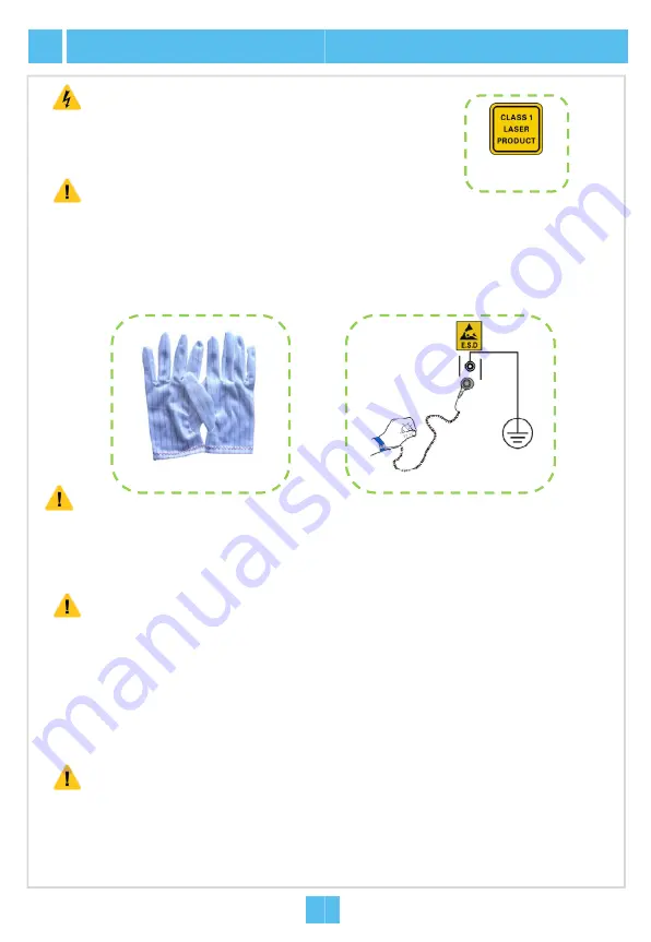
ESD Protection
Caution
To prevent laser radiation from injuring eyes,
end face of the fiber or fiber connector directl
Laser Safety
Warning
Carpets or other materials that easily gene
of the equipment room.
Do not touch any component or wires on c
measures should be taken if it is necessar
Before the equipment is powered on, the cabin
protection earth ground cable should be well g
resistance and ground resistance meet the spe
Grounding Requirements
Caution
Cables of different types on the installation
separately. Please note that optical fibers
Exercise care if you must bend fibers. If b
never be less than 20 d (d refers to the fib
Th
bl
b
d i h
d
Binding Cables
Caution
ESD protection gloves
2
2
The cables are bound with proper and equ
arranged in good order. The extra parts of
points.
Prior to equipment installation, please inspec
connection of cables (especially earth ground
that the conditions for installation are satisfac
documents. Please refer to the manual
Instal
Inspection Prior to Installation
Caution
erate static electricity should not be used on the floor
do not look into the
ly with naked eyes.
Laser class
identifier
erate static electricity should not be used on the floor
cards, or metal conductors in sockets. ESD protection
ry to touch the card during maintenance.
net protection earth ground cable and subrack
rounded. Check and ensure that the insulation
ecification.
n site should be laid out independently and bound
should be bound with dedicated fiber binding straps.
bends are necessary, the fiber bending radius should
ber diameter).
l
i
b
h
Th
bl bi d
ESD protection wrist strap
2
2
ual spacing between them. The cable binders are
f the binders are cut from the root without leaving sharp
ct the equipment room, cabinet, power supply,
d cable), and supporting facilities. After confirming
ctory, start the work following the project designing
llation Reference
for details.
Summary of Contents for AN5516-04
Page 1: ...MN000003108 AN5516 04 Optical Line Terminal Equipment Version D Quick Installation Guide...
Page 2: ......
Page 4: ......
Page 34: ......
Page 35: ......


