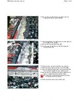
Remove the cover plate from the injector holes on
the cylinder head.
If present, fit the filler foam
(12)
in the relative seat.
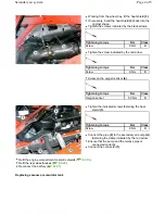
Fit the complete rail mounting
(11)
and fasten by
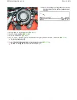
tightening the six screws indicated in the
sequence given in the photo aside.
Tightening torque
Nm
Class
Screw 10
Nm
B
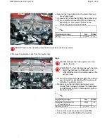
DO NOT remove the electroinjectors from the complete rail for any reason.
Remove the protector caps from the injector tips.
Fig. 2
NEVER lubricate the Teflon grommet on the
injector tip side.
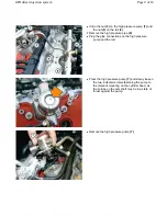
WARNING: The fuel rail complete with injectors
MUST be installed in a PARALLEL and
UNIFORM fashion in the relative seat on the
cylinder head.
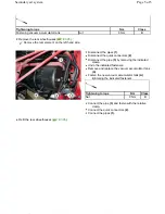
Fit the rail complete with injectors
(8)
in the relevant
seat, keeping the rail parallel with the seat and
installing in a uniform motion.
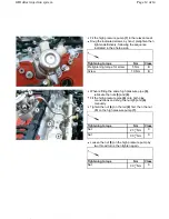
Manually snug the stud bolts (red arrows) and
screws (black arrows) indicated, then pretighten
and definitively tighten in the sequence given in
the photo aside.
Tightening torque
Nm
Class
Pretightening torque for
screw/stud bolt
5 Nm
B
Screw/stud bolt
10 Nm
B
Connect the pressure sensor connector
(13)
.
Connect the connectors
(10)
on the injectors.
Page 5 of 14
GDI direct injection system
8/5/2011
https://modiscs.ferrari.it/KnowledgeOnline/index.php?action=mo&link=link::SM_SM_F31...
Summary of Contents for 458 Italia
Page 1: ......
Page 24: ...1 7 Car Bench vehicle bench Copyright 2010 ...
Page 25: ...1 7 Car Bench vehicle bench Copyright 2010 ...
Page 26: ...1 7 Car Bench vehicle bench Copyright 2010 ...
Page 27: ...1 7 Car Bench vehicle bench Copyright 2010 ...
Page 28: ...1 7 Car Bench vehicle bench Copyright 2010 ...
Page 29: ...1 7 Car Bench vehicle bench Copyright 2010 ...
Page 30: ...1 7 Car Bench vehicle bench Copyright 2010 ...
Page 31: ...1 7 Car Bench vehicle bench Copyright 2010 ...
Page 522: ...Hook 95977564 AS 107564 for lifting the gearbox Page 5 of 5 Specific tooling and equipment ...
Page 586: ...In preparation Page 6 of 6 Engine overhaul Disassembly ...
Page 620: ...Perform the Fuel tank tightness test cycle Page 4 of 4 Fuel level sensor ...
Page 967: ...Refit the wheels D2 01 Page 10 of 10 Stabiliser bars Tie rods ...
Page 1127: ...Refit the wheels D2 01 Page 8 of 8 Wheelhouse ...
Page 1167: ...Prise out and remove the plug 4 Undo the nut 5 Undo the nut 6 Page 32 of 37 Doors ...
Page 1242: ...In the LOWEST position two movements are possible Page 8 of 12 Seats ...
Page 1243: ...In the INTERMEDIATE LOW position three movements are possible Page 9 of 12 Seats ...
Page 1244: ...In the INTERMEDIATE HIGH position three movements are possible Page 10 of 12 Seats ...
Page 1549: ...Reconnect the battery F2 01 Page 5 of 5 Starter motor ...
Page 1721: ...Charge the air conditioning system F5 12 Page 5 of 5 Condenser ...
Page 1740: ...Refit Page 13 of 13 A C unit ...
Page 1764: ...FD0001 Fuel supply distribution 0 99999 Page 10 of 56 PDF ...
Page 1765: ...FD0001 Fuel supply distribution 0 99999 Page 11 of 56 PDF ...
Page 1773: ...FD0001 Fuel supply distribution 0 99999 Page 19 of 56 PDF ...
Page 1774: ...FD0001 Fuel supply distribution 0 99999 Page 20 of 56 PDF ...
Page 1781: ...FD0001 Fuel supply distribution 0 99999 Page 27 of 56 PDF ...
Page 1782: ...FD0001 Fuel supply distribution 0 99999 Page 28 of 56 PDF ...
Page 1789: ...FD0001 Fuel supply distribution 0 99999 Page 35 of 56 PDF ...
Page 1790: ...FD0001 Fuel supply distribution 0 99999 Page 36 of 56 PDF ...
Page 1797: ...FD0001 Fuel supply distribution 0 99999 Page 43 of 56 PDF ...
Page 1798: ...FD0001 Fuel supply distribution 0 99999 Page 44 of 56 PDF ...
Page 1803: ...FD0001 Fuel supply distribution 0 99999 Page 49 of 56 PDF ...
Page 1804: ...FD0001 Fuel supply distribution 0 99999 Page 50 of 56 PDF ...
Page 1809: ...FD0001 Fuel supply distribution 0 99999 Page 55 of 56 PDF ...

