Exit
E5.04
Indications on the TFT display
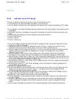
The driver is notified of a fault by the instrument panel via the following events:
The icon appears on the display simultaneously with the illumination of the warning light on the instrument panel
(if available).
All information contained in the display area reserved for messages is replaced by information concerning the
failure.
Faults are displayed according to the priority attributed to the faults themselves:
In the event of multiple simultaneous faults, the faults are displayed in order, with priority 0 faults first, priority 1
faults next and priority 2 faults last.
The information relative to the faults are displayed for 5 seconds each, in "rolling" order. with the screens
displayed in rolling mode and in order of priority or occurrence of the relative fault event.
If, during the display cycle for a fault, another priority 1 or 2 fault occurs, this will replace the message currently
displayed only once the latter has been displayed for 2 seconds. The messages then continue to be
displayed in "rolling" order.
If, during the display cycle for a fault, a priority 0 fault occurs, this will replace the fault currently displayed
immediately, without waiting 2 seconds. The messages then continue to be displayed in "rolling" order.
During the display of multiple faults in rolling order, if any of the faults is interrupted by a new failure/check event
before its full display period has elapsed, the last event will be displayed nonetheless for 5 seconds, even if a
shorter period would suffice to complete its display cycle.
During the display of priority 0, 1 and 2 faults, the set-up MENU functions, which are normally accessible via the
specific buttons, are disabled.
During the display of priority 0, 1 and 2 faults, the display of other main screens normally accessible with the
specific DISP button is disabled.
The faults remain displayed for 20 seconds.
In the event of faults with no physical warning light on the instrument panel, at the end of the display cycle, the
relative symbol will be shown in icon form in area C1 of the display and will remain displayed until the
malfunction generating the fault has been rectified.
In the event of faults with a physical warning light on the instrument panel, at the end of the display cycle, the
relative symbol will not be shown in icon form in area C1 of the display.
Additionally, the screen displayed before the fault event will be shown again.
The fault is displayed for the period specified above at each key-on (until the malfunction generating the fault
has been rectified).
If the fault is rectified before the end of the display cycle, the message will continue to be displayed and the
relative warning light (if available) will remain lit for at least 2 seconds, to prevent undesirable "flashing"
effects.
The warning light (if available) extinguishes and the message disappears from the display simultaneously.
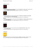
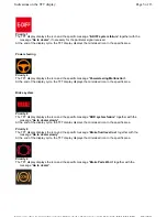
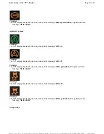
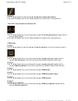
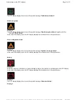
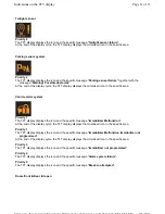
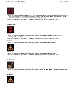
relevant fault warning light (if available) illuminated on instrument panel;
icon (if available) corresponding to fault displayed with relative specific message (if available) on TFT display;
Priority 0 (very serious)
Priority 1 (serious)
Priority 2 (not serious)
Page 1 of 13
Indications on the TFT display
8/5/2011
https://modiscs.ferrari.it/KnowledgeOnline/index.php?action=mo&link=link::SM_SM_E50...
Summary of Contents for 458 Italia
Page 1: ......
Page 24: ...1 7 Car Bench vehicle bench Copyright 2010 ...
Page 25: ...1 7 Car Bench vehicle bench Copyright 2010 ...
Page 26: ...1 7 Car Bench vehicle bench Copyright 2010 ...
Page 27: ...1 7 Car Bench vehicle bench Copyright 2010 ...
Page 28: ...1 7 Car Bench vehicle bench Copyright 2010 ...
Page 29: ...1 7 Car Bench vehicle bench Copyright 2010 ...
Page 30: ...1 7 Car Bench vehicle bench Copyright 2010 ...
Page 31: ...1 7 Car Bench vehicle bench Copyright 2010 ...
Page 522: ...Hook 95977564 AS 107564 for lifting the gearbox Page 5 of 5 Specific tooling and equipment ...
Page 586: ...In preparation Page 6 of 6 Engine overhaul Disassembly ...
Page 620: ...Perform the Fuel tank tightness test cycle Page 4 of 4 Fuel level sensor ...
Page 967: ...Refit the wheels D2 01 Page 10 of 10 Stabiliser bars Tie rods ...
Page 1127: ...Refit the wheels D2 01 Page 8 of 8 Wheelhouse ...
Page 1167: ...Prise out and remove the plug 4 Undo the nut 5 Undo the nut 6 Page 32 of 37 Doors ...
Page 1242: ...In the LOWEST position two movements are possible Page 8 of 12 Seats ...
Page 1243: ...In the INTERMEDIATE LOW position three movements are possible Page 9 of 12 Seats ...
Page 1244: ...In the INTERMEDIATE HIGH position three movements are possible Page 10 of 12 Seats ...
Page 1549: ...Reconnect the battery F2 01 Page 5 of 5 Starter motor ...
Page 1721: ...Charge the air conditioning system F5 12 Page 5 of 5 Condenser ...
Page 1740: ...Refit Page 13 of 13 A C unit ...
Page 1764: ...FD0001 Fuel supply distribution 0 99999 Page 10 of 56 PDF ...
Page 1765: ...FD0001 Fuel supply distribution 0 99999 Page 11 of 56 PDF ...
Page 1773: ...FD0001 Fuel supply distribution 0 99999 Page 19 of 56 PDF ...
Page 1774: ...FD0001 Fuel supply distribution 0 99999 Page 20 of 56 PDF ...
Page 1781: ...FD0001 Fuel supply distribution 0 99999 Page 27 of 56 PDF ...
Page 1782: ...FD0001 Fuel supply distribution 0 99999 Page 28 of 56 PDF ...
Page 1789: ...FD0001 Fuel supply distribution 0 99999 Page 35 of 56 PDF ...
Page 1790: ...FD0001 Fuel supply distribution 0 99999 Page 36 of 56 PDF ...
Page 1797: ...FD0001 Fuel supply distribution 0 99999 Page 43 of 56 PDF ...
Page 1798: ...FD0001 Fuel supply distribution 0 99999 Page 44 of 56 PDF ...
Page 1803: ...FD0001 Fuel supply distribution 0 99999 Page 49 of 56 PDF ...
Page 1804: ...FD0001 Fuel supply distribution 0 99999 Page 50 of 56 PDF ...
Page 1809: ...FD0001 Fuel supply distribution 0 99999 Page 55 of 56 PDF ...

