Using a mobile hydraulic hoist with a minimum load
capacity of
300 Kg
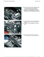
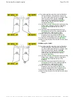
, position the lift hook over the
engine.
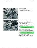
Use a suitable strap
(39)
to fasten the hook
(
AV 3979
)
to the hoist.
Using two suitably sized straps
(41)
and carabiners,
connect the hook
(
AV 3979
)
to the brackets
(
AV 8252
)
fastened previously to the exhaust
stud bolts.
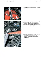
Using a suitably sized strap
(42)
and carabiners,
connect the lift tool
(
AV 3432
)
mounted
previously onto the crankcase stud bolts to the
hydraulic hoist.
Tauten the hoist straps with the mobile hydraulic
hoist.
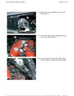
Remove the block
(F)
fitted previously.
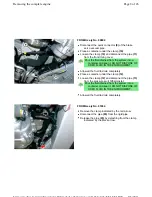
On both sides, undo the screws
(42)
fastening the
engine strut to the engine mounting bush,
retrieving the relative washer.
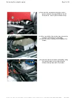
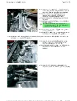
Lift the engine by a few millimetres, ensuring that
the strap tension is uniform and that the engine
itself lifts evenly.
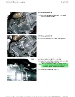
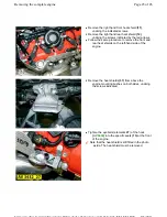
On the right-hand side only (as shown in the photo
aside), undo the screws indicated and remove
the engine mounting bush
(43)
, to allow enough
room for the engine to be lifted past the oil pump.
Retrieve the retainer bracket
(44)
.
Page 16 of 26
Removing the complete engine
8/5/2011
https://modiscs.ferrari.it/KnowledgeOnline/index.php?action=mo&link=link::SM_SM_B20...
Summary of Contents for 458 Italia
Page 1: ......
Page 24: ...1 7 Car Bench vehicle bench Copyright 2010 ...
Page 25: ...1 7 Car Bench vehicle bench Copyright 2010 ...
Page 26: ...1 7 Car Bench vehicle bench Copyright 2010 ...
Page 27: ...1 7 Car Bench vehicle bench Copyright 2010 ...
Page 28: ...1 7 Car Bench vehicle bench Copyright 2010 ...
Page 29: ...1 7 Car Bench vehicle bench Copyright 2010 ...
Page 30: ...1 7 Car Bench vehicle bench Copyright 2010 ...
Page 31: ...1 7 Car Bench vehicle bench Copyright 2010 ...
Page 522: ...Hook 95977564 AS 107564 for lifting the gearbox Page 5 of 5 Specific tooling and equipment ...
Page 586: ...In preparation Page 6 of 6 Engine overhaul Disassembly ...
Page 620: ...Perform the Fuel tank tightness test cycle Page 4 of 4 Fuel level sensor ...
Page 967: ...Refit the wheels D2 01 Page 10 of 10 Stabiliser bars Tie rods ...
Page 1127: ...Refit the wheels D2 01 Page 8 of 8 Wheelhouse ...
Page 1167: ...Prise out and remove the plug 4 Undo the nut 5 Undo the nut 6 Page 32 of 37 Doors ...
Page 1242: ...In the LOWEST position two movements are possible Page 8 of 12 Seats ...
Page 1243: ...In the INTERMEDIATE LOW position three movements are possible Page 9 of 12 Seats ...
Page 1244: ...In the INTERMEDIATE HIGH position three movements are possible Page 10 of 12 Seats ...
Page 1549: ...Reconnect the battery F2 01 Page 5 of 5 Starter motor ...
Page 1721: ...Charge the air conditioning system F5 12 Page 5 of 5 Condenser ...
Page 1740: ...Refit Page 13 of 13 A C unit ...
Page 1764: ...FD0001 Fuel supply distribution 0 99999 Page 10 of 56 PDF ...
Page 1765: ...FD0001 Fuel supply distribution 0 99999 Page 11 of 56 PDF ...
Page 1773: ...FD0001 Fuel supply distribution 0 99999 Page 19 of 56 PDF ...
Page 1774: ...FD0001 Fuel supply distribution 0 99999 Page 20 of 56 PDF ...
Page 1781: ...FD0001 Fuel supply distribution 0 99999 Page 27 of 56 PDF ...
Page 1782: ...FD0001 Fuel supply distribution 0 99999 Page 28 of 56 PDF ...
Page 1789: ...FD0001 Fuel supply distribution 0 99999 Page 35 of 56 PDF ...
Page 1790: ...FD0001 Fuel supply distribution 0 99999 Page 36 of 56 PDF ...
Page 1797: ...FD0001 Fuel supply distribution 0 99999 Page 43 of 56 PDF ...
Page 1798: ...FD0001 Fuel supply distribution 0 99999 Page 44 of 56 PDF ...
Page 1803: ...FD0001 Fuel supply distribution 0 99999 Page 49 of 56 PDF ...
Page 1804: ...FD0001 Fuel supply distribution 0 99999 Page 50 of 56 PDF ...
Page 1809: ...FD0001 Fuel supply distribution 0 99999 Page 55 of 56 PDF ...


