Appendix - Specifications
ComTec GmbH
Appendix 8-3
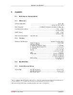
Input amplitude:
(clipped sine or sine wave).............................................. typ. 3.3 V
PP
The clock I/O circuitry is widely adjustable to individual needs.
Contact factory for details.
ADC ports
Connectors:
......................................................................... 25 pin female D-SUB
Input Impedance:
......................................................................................10 k
Ω
pull-up
Output impedance:
(series resistor)..........................................................33
Ω
/ 0.063 W
Input HIGH voltage:
........................................................................................... min. 2.0 V
Input LOW voltage:
.......................................................................................... max. 0.8 V
Output HIGH voltage:
I
OH
= -1.0 mA ..................................................................... min. 2.4 V
I
OH
= -4.0 mA ..................................................................... min. 2.2 V
Output LOW voltage:
I
OL
= 1.0 mA...................................................................... max. 0.4 V
I
OL
= 8.0 mA...................................................................... max. 0.7 V
DRDY to DACC time:
.........................................................................................min. 211 ns
4 ADC's simultaneously in a row................................ max. 897 ns
11
ADC GATE inputs
Connector:
.....................................................15 pin high-density female D-SUB
Input Impedance:
......................................................................................10 k
Ω
pull-up
Input HIGH voltage:
........................................................................................... min. 2.0 V
Input LOW voltage:
.......................................................................................... max. 0.8 V
Gate setup time:
Gate to DRDY ...................................................................... - 211 ns
Gate hold time:
Gate after end of DRDY .......................................................... ~ 0 ns
Digital I/O 0...7
Location:
........................................... ref. FEATURE (multi) I/O port connector
R PULL :
(default) ..................................................................................1.0 k
Ω
R I/O:
(default) .....................................................................................22
Ω
Input HIGH voltage:
(at PIN
i
)
12
......................................................................... min. 2.0 V
Input LOW voltage:
(at PIN
i
) ............................................................................ max. 0.8 V
Output HIGH voltage:
(at POUT
i
) I
OutHIGH
= -4.0mA ............................................. min. 2.4 V
Output LOW voltage:
(at POUT
i
) I
OutLOW
= 8.0mA .............................................. max. 0.4 V
GO-Line
Location: ...................................................................................................
BNC
.......................................... ref. FEATURE (multi) I/O port connector
Line type:
......................................................................open drain / wired-AND
Pull-up resistor:
................................................................................... 22k
Ω
to +5.0 V
11 ADC data in a port row (1..4 or 5...8) is queued for transfer. Thus, simultanously firing ADC's may delay the interface response
by 211 ns. Interface operates at 19 MHz or 53 ns. Max. DRDY-to-DACC = 4 x 211 ns + 53 ns = 897 MHz.
12 Note: input and output voltages are measured at the internal logic pads not at the external connectors. Thus, the corresponding
pull and series resistors must be considered to get the external voltages

