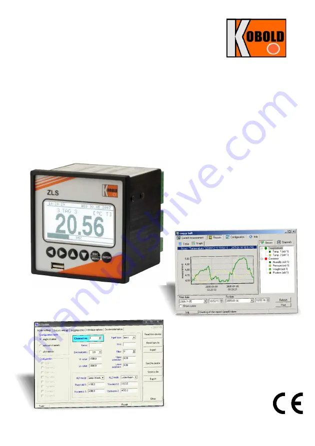
background image

User manual

 for

DATA RECORDER

Firmware: 

v.3.36 b3

 or higher

Logy

 Soft: 

v.1.10.0

 or higher

S-Toolkit: 

v.2.1.0

 or higher

Read the user's manual carefully before starting to use the unit or software. 

Producer reserves the right to implement changes without prior notice.

Logy

 Soft

S-Toolkit

Model: ZLS-2

Summary of Contents for ZLS-2

Page 1: ...3 or higher Logy Soft v 1 10 0 or higher S Toolkit v 2 1 0 or higher Read the user s manual carefully before starting to use the unit or software Producer reserves the right to implement changes witho...

Page 2: ...LE OF OUTPUTS OPERATION 37 6 3 1 Alarms 37 6 3 2 Outputs control 38 6 3 3 Example of output control 40 7 DEVICE PROGRAMMING 41 7 1 PARAMETERS EDITION 43 7 1 1 Numeric and switching parameters LIST typ...

Page 3: ...tab 94 3 3 CONFIGURATION MENU 99 3 3 1 Devices tab 100 3 3 2 Groups tab group operations 104 3 3 3 Settings tab 106 3 4 LIST OF ERRORS AND FAULT DIAGNOSTICS 108 III USER MANUAL FOR S TOOLKIT 109 1 GEN...

Page 4: ...changes the instruction manuals available online may not always correspond to the product version you have purchased If you need an instruction manual that corresponds to the purchased product versio...

Page 5: ...r is responsible for executing the installation according to this manual local safety and EMC regulations The unit must be properly set up according to the application Incorrect configuration can caus...

Page 6: ...internal analogue digital converter has a 12 or 16 bit resolution depending on input type which provides high measurement resolution results Additionally individual alphanumeric description text of ea...

Page 7: ...data recorder It allows the display of trend graphs for each channel separately Different operation modes provide the possibility of selecting and adjusting the method of data presentation depending...

Page 8: ...in 500 V DC Digital outputs 2 electronic relays NO type 24 V AC 35 V DC max 200 mA overload protection Recording cycle 1 sec 2 sec 5 sec 10 sec 15 sec 20 sec 30 sec 1 min 2 min 5 min 10 min 15 min 20...

Page 9: ...t inputs type This manual contain following short descriptions U I version means device with type of inputs voltage 0 5 V 1 5 V 0 10 V 2 10 V current 0 20 mA 4 20 mA mV RTD TC version means device wit...

Page 10: ...K J E 0 1 25 C one digit N 0 2 25 C one digit S T R B 0 5 25 C one digit Accuracy of cold ends temperature compensation 1 C RTD input Pt100 Pt500 or Pt1000 with manual connection switch 2 or 3 wire Me...

Page 11: ...ndows environment S Toolkit PC software for data logger easy configuring Logy Soft PC software for moving reporting archiving and displaying recorded data This is a class A unit In a residential or a...

Page 12: ...al voltage stated on the unit s identification label The load must correspond to the requirements listed in the technical data All installation works must be conducted with a disconnected power supply...

Page 13: ...the unit a 90 5 x 90 5 mm mounting hole Fig 4 1 must be prepared The thickness of the material of which the panel is made must not exceed 5mm When preparing the mounting hole take the grooves for catc...

Page 14: ...4 2 Allowable mounting hole dimensions Fig 4 3 Installing of brackets and dimensions of connectors 14 92 mm max 5 mm 90 5 mm 92 mm 8 mm 12 mm 10 mm 8 5 mm 16 mm removable terminals NOTE U I version re...

Page 15: ...ECTION METHOD Caution Installation should be conducted by qualified personnel During installation all available safety requirements should be considered The fitter is responsible for executing the ins...

Page 16: ...on to their correct tightening or clamping In the case of any doubt consider using additional preventive measures covers roofing seals etc Carelessly executed assembly can increase the risk of electri...

Page 17: ...e insulation replacing and cable terminals dimensions All connections must be made while power supply is disconnected Depending on version 85 230 260 V AC DC or 19 24 50 V DC 16 24 35 V AC Fig 4 7 Con...

Page 18: ...9 Connection of USB transmission signals Fig 4 10 Connection of digital input depending on data recorder configuration 18 24 V DC external supply DIN recording enable external switch DIN RS 485 data...

Page 19: ...optional PE GND U1 GND 24 V U2 U3 U4 U5 U6 U7 U8 24 V additional terminals internally connected USB PC Host USB optional RS 485 data data GND n c din din 48 47 46 45 44 43 42 41 40 39 38 37 36 35 34...

Page 20: ...rs sensor power supply voltage and 4 20 mA signal 20 36 35 34 33 32 31 30 29 28 27 26 25 Inp 1 4 20 mA external GND connection Inp 8 0 10 V 24 23 22 21 20 19 18 17 16 15 14 13 additional terminals int...

Page 21: ...wire circuit is used the resistance of wires should be as small as possible to avoid of measurement errors Measured value can be corrected constant correction using Bias parameter from menu Input sett...

Page 22: ...nge 4 4 MAINTENANCE The unit does not have any internal replaceable or adjustable components available to the user Pay attention to the ambient temperature in the room where the unit is operating Exce...

Page 23: ...bols used in the manual ENTER Functions start editing parameter go to submenu confirm change of edited parameter Symbols used in the manual Functions change the horizontal cursor position modify edite...

Page 24: ...ace do not stops the data recording process Results of measurements conducted for active selected by the user channels of the unit are displayed in one of the available result presentation modes see R...

Page 25: ...measured signal is selectable and user defined as user defined range All values presented in graphic form graphs sliders are scaled due to user defined range The range of the results referred to maxim...

Page 26: ...d signals it is possible to set the unit s options to record averaged measurement results Setting the recorded value type to averaged value parameters Channel 1 Channel 8 depending on the number of ch...

Page 27: ...omentary measurement value or averaged measurement results Recording the measurement results in the non volatile memory can be executed in two modes until full or cyclic Write parameter The first mode...

Page 28: ...nables the last measurement for one of the measurement channels to be viewed in the numeric and graphic form bar Fig 6 7 Single channel mode Measurements list mode Fig 6 8 enables the momentary values...

Page 29: ...puts settings menu Fig 6 12 Unit in Single channel result presentation mode Exceeding the user defined range Fig 6 13 is signalled on the bar with an arrow indicating the direction of exceeding the ra...

Page 30: ...or Lo message is displayed depending on the direction of exceeding see description of Upper ext and Lower ext parameters in the Inputs settings menu In order to go to the Measurements list options me...

Page 31: ...through the measurement list the List type Date and Time parameters in the Measurements list options are set automatically depending on the time and date of the currently displayed measurement result...

Page 32: ...ta to be displayed from the unit s memory recorded measurement results an appropriate message is displayed instead of the measurement result Fig 6 17 X is displayed for data that has not been download...

Page 33: ...eds the graph scale range Fig 6 19 6 20 instead of the current numeric value displayed in the upper right corner the display shows a Hi or Lo message depending on the direction of exceeding Fig 6 19 E...

Page 34: ...is range by at least one of the measurements to be averaged In the case of the upper limit lower limit or both limits of measurement range being exceeded in the given recording period values represent...

Page 35: ...of the data downloaded so far X will be displayed instead of data that was not downloaded Fig 6 23 Fig 6 23 Display in Graph mode in the case where data download was stopped 6 2 4 Channels List mode I...

Page 36: ...ress the ESC MENU key to go to Channels list options menu Fig 6 25 Unit in Channels list results presentation mode Channels list options parameter set as values Functions of keys in Channels list mode...

Page 37: ...menu Fig 6 26 Screen with relay 1 open and relay 2 closed 6 3 1 Alarms Each channel can generate two independent alarms Particular alarm is present when entered condition is met Those conditions can b...

Page 38: ...ction is 1 and closed in the other case Fig 6 29 shows example reading fallowed by rely state Rely state can be changed only when times tA tB tC tD are greater than delays times If those delays times...

Page 39: ...tput is hold alarms states are no consider therefore no delays times are counted until hold time elapsed Fig 6 31 Working output controlled by single channel alarm with large reading oscillations Alar...

Page 40: ...to control the cooler The input channel where temperature sensor is connected must be configured correctly in this example it is assumed reading is in Celsius degree If lower limit of the temperature...

Page 41: ...e configuration menu of selected results presentation mode press the ESC MENU key in the current results presentation mode The unit s main menu Fig 7 1 enables necessary information about the unit to...

Page 42: ...of current menu item if the menu item corresponds to one of the unit s parameters pressing ENTER starts parameter editing if the menu item selects a lower level menu pressing ENTER activates the new m...

Page 43: ...list out of which only one of the options available on the list can be selected for the given parameter Options of switching parameter are selected using v keys Fig 7 4 Editing numerical parameter Fi...

Page 44: ...surrounding the edited character Fig 7 6 Selection of character for editing Functions of keys when selecting character for editing characters table is not displayed at that time Selecting the position...

Page 45: ...as the last one in the sequence Cancel changes at any time 7 1 3 SLIDER type parameters The parameters of this type are presented graphically in the form of a bar that turns black correspondingly to t...

Page 46: ...lower part of the display in negative represents the result of the current not recorded yet measurement The measurement results recorded so far stored in the non volatile memory for the given channel...

Page 47: ...date when the unit was switched on last 7 2 2 Graph options menu This menu contains options configuring the method of displaying measurement results for the Graph mode Scale this option allows time po...

Page 48: ...ESC ENTER Display Parameter edition Mode Channels list Mode Single channel MENU ESC MENU ESC MENU ESC Measurements list options Date MENU ESC Graph options Scale Mode Graph MENU ESC MENU ESC ENTER ME...

Page 49: ...ed message is displayed depending on the set value of the Write parameter in the Logging setup menu The calculated Time left time is an approximated value Download the recorded data to your PC before...

Page 50: ...ormation menu the display will show the Logging stopped message The recording will be restarted only when the collected measurement results are downloaded to a PC once unit s memory is free If the col...

Page 51: ...parameter defines the interval for measurement recording 15 options are available 1 sec 2 sec 5 sec 10 sec 15 sec 20 sec 30 sec 1 min 2 min 5 min 10 min 15 min 20 min 30 min 60 min Measurements are sy...

Page 52: ...a given channel then this channel will not be available on the list of recording channels in the Logging setup menu Fig 7 18 Recording points depending on Triggering parameter value 52 i disabled dis...

Page 53: ...e Under threshold alarm is generated when displayed value in this channel is under entered value Over threshold alarm is generated when displayed value in this channel is over entered value Threshold...

Page 54: ...displayed value is defined by Hi value Lo value and Dec point parameters Hi value Lo value these parameters define the values displayed for maximum Hi and minimum Lo current voltage of user defined ra...

Page 55: ...be displayed instead of the measurement result in numeric form The Upper extension and Lower extension values are defined in mA or V with the accuracy of 0 01 mA or 0 01 V The Lower extension value is...

Page 56: ...ting the unit for the value measured on the given channel Input type type of input sensor The following options are available inactive input is not active 60 mV 75 mV 100 mV 150 mV milivoltage inputs...

Page 57: ...point for results displayed in numerical form The following options are available 0 0 0 0 00 0 000 The position of the decimal point is selected with v keys Upper ext Lower ext These parameters are av...

Page 58: ...s active state computing method for attached alarms The following options are available OR output is active when any of the attached channels is alarm state AND output is active when all of the attach...

Page 59: ...riggering signal disappears All time type parameters which describe outputs can be set in range 0 9999 with resolution of 1 sec Because of computing precision the time is shorter about 2 5 than the en...

Page 60: ...7600 115200 b sec Default baud rate value is 115200 b sec Some RS 485 converters may not work properly with this setting In such a case set lower baud rate according to converter data sheet Resp delay...

Page 61: ...digit number If the parameter is set to 0000 the password is disabled If the parameter is different from 0000 then menu access requires password to be entered If the user do not remember his password...

Page 62: ...guration FlashDrive should be unplugged or any key pressed If error occurs while reading or writing proper message is displayed User have to confirm this message using ENTER Automatic write of registe...

Page 63: ...egister the disk or disable of Password for USB disk write While Auto data write is active and FlashDisk is plugged to USB connector pressing the ENTER key in any presentation mode will force the stor...

Page 64: ...Lo value Filter Hi value Upper ext Lower ext Dec point MENU ESC Inputs settings ENTER MENU ESC ENTER MENU ESC Name Unit Parameter edition Rec period Channel 8 Triggering ENTER ENTER MENU ESC ENTER Wri...

Page 65: ...MENU ESC MENU ESC Access setup ENTER ENTER MENU ESC ENTER Password for menu access Parameter edition Register the disk Read config from disk MENU ESC MENU ESC USB options ENTER ENTER MENU ESC ENTER W...

Page 66: ...ser must select and use one of them 8 3 USB FLASH DRIVE PENDRIVE DATA DOWNLOAD If data logger is equipped with USB Host interface then the stored data can be downloaded from the data logger without PC...

Page 67: ...ew seconds to three minutes A progress bar is displayed during the data write After successful data write the following message will appear which has to be confirmed by pressing ENTER key In order to...

Page 68: ...ing can be forced but it may cause errors 3 When pendrive is formatted not in accordance with Tab 8 1 file writing not done If some error occurs during measurement writing one of following messages wi...

Page 69: ...puts version range 1000 6000 for C 1480 11120 for F Register from 02h1 to 08h1 Measurement result for channel 2 8 registry description like for channel 1 see registers 01h 09h No 0 0FFFFh Information...

Page 70: ...stries contents 2 date update on the basis of 18h 1Bh registries contents 3 time and date update on the basis of 18h 1Eh registries contents After sending commands 1 2 or 3 the contents of registries...

Page 71: ...sidering decimal point 42h Yes 9999 9999 Hi value parameter in Inputs settings submenu for channel 1 not considering decimal point 43h Yes 0 3 Dec point parameter in Inputs settings submenu for channe...

Page 72: ...7 Lower byte character No 8 4Bh Yes Character Name parameter in Inputs settings submenu for channel 1 Higher byte character No 9 Lower byte 0 4Ch Yes Character Unit parameter in Inputs settings subme...

Page 73: ...ttings submenu for channel 4 registry description like for channel 1 see registers C0h to C5h Register from E0h to E5h Alarm parameters in Inputs settings submenu for channel 5 registry description li...

Page 74: ...in Outputs settings submenu for output 1 Register from 110h to 11Dh Parameters in Outputs settings submenu for output 2 registry description like for output 1 see registers 100h to 10Dh 1 if the meas...

Page 75: ...mber of higher bytes in the frame DATA H LHigher and lower part of data word CRC L H Higher and lower part of CRC sum 1 Read of ID code ADDR FUNC REG H L COUNT H L CRC L H 01 03 00 21 00 01 D4 00 The...

Page 76: ...ecimal point DATA H2 L2 02h registry 2 value displayed for channel 2 no decimal point DATA H3 L3 03h registry 640 value displayed for channel 3 no decimal point 5 Setting of name for channel 1 as Chan...

Page 77: ...meter in RS485 port settings menu 6 Change of baud rate of all devices connected to the net BROADCAST message ADDR FUNC REG H L COUNT H L CRC L H 00 06 00 22 00 04 29 D2 DATA H 0 DATA L 4 new baud rat...

Page 78: ...sed memory 48 Time left Time until memory is full 48 Parameters in the Display options menu Backlight Method of display backlight operation 48 Brightness Brightness of display backlight 48 Contrast Di...

Page 79: ...s of alarm 1 52 AL2 mode Alarm 2 generation mode 52 Threshold 2 Threshold of alarm 2 52 Hysteresis 2 Hysteresis of alarm 2 52 Settings for Channel 2 in Inputs settings menu Name Measurement channel na...

Page 80: ...easurement range 54 AL1 mode Alarm 1 generation mode 52 Threshold 1 Threshold of alarm 1 52 Hysteresis 1 Hysteresis of alarm 1 52 AL2 mode Alarm 2 generation mode 52 Threshold 2 Threshold of alarm 2 5...

Page 81: ...as Shifting of measurement scale 57 Upper ext Upper extension of measurement range 54 Lower ext Lower extension of measurement range 54 AL1 mode Alarm 1 generation mode 52 Threshold 1 Threshold of ala...

Page 82: ...minimum value of input current 53 56 Dec point Position of the decimal point 54 Filter Level of filtration of indications 52 Bias Shifting of measurement scale 57 Upper ext Upper extension of measurem...

Page 83: ...te source 57 Source channel 3 Channel 3 alarm state source 57 Source channel 4 Channel 4 alarm state source 57 Source channel 5 Channel 5 alarm state source 57 Source channel 6 Channel 6 alarm state s...

Page 84: ...e 58 Closed hold time Time for holding the closed state 58 Open hold time Time for holding the open state 58 Parameters in the RS485 port settings menu Address Device address 59 Baud rate Baud rate 59...

Page 85: ...85...

Page 86: ...12 EU DECLARATION OF CONFORMANCE 86...

Page 87: ...2 During installation follow the directions provided by Installation wizard The wizard will create a folder called Logy Soft on the computer s hard drive the program files will be placed in this fold...

Page 88: ...Next button Prior to scanning the network for devices set the addresses identifying the selected devices in the network a different address for each device see page 59 In order to detect units connec...

Page 89: ...anning button Properties list available in right part of the window allows configuration of measurement channels Appropriate names e g the location where the sensor connected to this channel was insta...

Page 90: ...w Fig 3 1 Three positions are available Current measurement menu for current measurements visualizing Reports menu for visualizing and printing reports Configuration menu for changing system settings...

Page 91: ...rement mode Presently read data will be showed in column named Current measurement Fig 3 2 Current measurement menu 3 2 REPORTS MENU Reports menu is used to view and print reports containing recorded...

Page 92: ...ber of channels is displayed in the centre of the tab The remaining elements of the Table tab are From date this is the date and time defining the beginning of analysed measurement recording period fo...

Page 93: ...irst Creating groups is described in the Group operations section 3 3 2 page 101 Change of From date or To date 1 In order to change From date or To date date click onto the arrow on right side of the...

Page 94: ...midity in the form of a graph Measurements from a maximum of five recorded measurement channels can be viewed The Graph tab contains such elements as graphs area plots measured values e g temperature...

Page 95: ...ific group or measurement channel This will display measurement results for the selected group or single channel displaying results takes place automatically after each change of group or measurement...

Page 96: ...e Fig 3 7 Enlarging graph moving the graph the graph can be moved to the left right earlier later time period correspondingly In order to do this right click on the graph and drag the pointer in desir...

Page 97: ...n until cursor became same colour as desired channel Near to the cursor informations about selected point are displayed Date and time of recording and value of the registered measurement point Fig 3 9...

Page 98: ...ed on the graph as interruption in the measurement Fig 3 10 Fig 3 10 Interruption in the graph e g sensor fault If measurements can not be executed for some time e g power supply fault or the device i...

Page 99: ...Configuration menu is used to change the settings of channels of devices working in the system and getting data from these devices Devices tab operations of groups Groups tab change the settings of pr...

Page 100: ...User manual DATA RECORDER and cooperating software Fig 3 13 Configuration menu advanced options active 3 3 1 Devices tab Fig 3 14 Configuration Devices tab advanced options active 100...

Page 101: ...ist of properties of selected device or channel All parameter s values underlined can be edited All changed but not approved using Apply values are showed in bold Apply and Revert buttons allow to mem...

Page 102: ...oad data file button This method should be used only if the logged data was previously copied manually from FlashDrive to PC hard drive Data downloading via RS 485 interface Default settings of data d...

Page 103: ...utes and data downloaded lastly were stored 2009 07 28 17 15 then set parameter From date omitting one or more data points To omit one point only set 2009 07 28 17 45 and click Download data RS485 aga...

Page 104: ...roups tab group operations Fig 3 18 Configuration Groups tab A group enables creating a collective current graph report for a number of measurement channels belonging to the same or to different devic...

Page 105: ...sired group on the Groups list click on the group again the group name will be highlighted the name can be edited The edit can be cancelled restore previous name by pressing the ESC key Upon completin...

Page 106: ...found contain new data program will display relevant information or data will be imported automatically if the option Automatically find and import all new data is enabled Automatically find and impor...

Page 107: ...options field settings that are here affect the way of creation a file from generated data using the Export button accessible from Reports menu These settings include Exclude Min Max info if this opt...

Page 108: ...mputer s serial port e g by connecting mouse to the port supporting the converter Some points are a red colour and question marks are displayed instead of current values Transmission line fault check...

Page 109: ...h ZLS selection of device type ZLS 1 2 In addition the software is on the supplied CD During installation follow the directions provided by Installation wizard The wizard will create a folder called S...

Page 110: ...ith computer s time and date Device information this tab allows obtaining basic information about the unit and update the unit s firmware In the right part of the window there are six buttons Read fro...

Page 111: ...from the channels available in the device all channels options enables setting configuration parameters for all channels at the same time selected channels option enables setting configuration parame...

Page 112: ...t depends on the type of device being configured 3 2 OUTPUTS SETTINGS TAB This tab contains options for configuring device outputs Detailed description of individual parameters can be found in the use...

Page 113: ...port settings in this section define the address of configured device transmission speed for the serial interface and the number of the serial port to which the configured device is connected In order...

Page 114: ...omputer s time and date Fig 3 5 Interface options tab functions If device clock shows later time than computer s system clock then the synchronization in this case reversing device clock will cause al...

Page 115: ...function Memory erase should be done ONLY IN EXCEPTIONAL SITUATION During normal operation of device in both mode cyclic and until full memory erasing IS NOT REQUIRED With memory erasing all measurem...

Page 116: ...nfiguration mode the parameters values of most recently configured channel remain in the configuration fields If the parameters for selected channels will be modified then the change of channel config...

Page 117: ...utton is active if the updating software version is newer than the device software In exceptional cases update interrupted or unit does not operate after update contact the manufacturer The newest ver...

Reviews: